Table of Contents
Advertisement
Advertisement
Table of Contents

Related Manuals for Trane VAV-UCM 4.2


Summary of Contents for Trane VAV-UCM 4.2
- Page 1 Installation Operation Maintenance VAV-UCM 4.2 VAV-SVX01C-EN May 2010...
- Page 2 Should equipment failure occur, contact a qualified service organization with qualified, experienced HVAC technicians to properly diagnose and repair this equipment. © 2010 Trane All rights reserved VAV-SVX01C-EN...
-
Page 3: Table Of Contents
Table of Contents General Information ........... . 6 Chapter Overview . - Page 4 Table of Contents UCM Programming and Operation ........30 Chapter Overview .
- Page 5 VAV Proportional Hot water failure ......77 Trane/Honeywell Proportional valve check out procedures .
-
Page 6: General Information
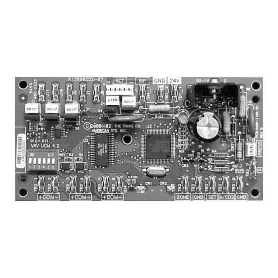
General Information Chapter Overview This chapter contains information about the following: • Unit Control Module 4.2 (UCM 4.2) • Specifications • UCM 4.2 Enhancements • UCM 4.2 Features • Shipping • Storage Unit Control Module 4.2 (UCM 4.2) The UCM 4.2 is a microprocessor-based, Direct Digital Controller (DDC) for the (Variable Air Volume) VAV terminal unit. -
Page 7: Ucm 4.2 Enhancements
General Information UCM 4.2 Enhancements • The enhanced VAV UCM is backward compatible with VariTrane® D VAV boxes (VXXD and VXXE) VariTrac® dampers, and VariTrac II dampers. • UCM 4.2 adds support for operation with VariTrane Series F valves (¼-turn blade dampers) via 90-second drive time. -
Page 8: Shipping
Up to three (3) UCM 4.2 may be connected to a single zone sensor. Generic UCM Capability UCM 4.2 can be configured to control non-Trane VAV boxes. Shipping Each VAV product and its service literature are shipped in the same package. When unpacking, make sure that the literature is not lost or discarded with the packing material. -
Page 9: Storage
General Information before leaving the factory. Any claims for damage incurred during shipment must be filed with the carrier. Storage When any component of the VAV system and/or field installed accessories must be stored for a period of time prior to being installed, they must be protected from the elements. The storage location temperature should be between -40°... -
Page 10: Vav Start Up/Check Out Procedure
VAV Start Up/Check Out Procedure Chapter Overview This chapter contains information about the following: • Unit 4.2 Pre-Power Check-Out • Light Emitting Diode (LED) Operations • Zone Sensor Check-Out UCM 4.2 Pre-Power Check-Out WARNING Live Electrical Components! During installation, testing, servicing and troubleshooting of this product, it may be necessary to work with live electrical components. -
Page 11: Zone Sensor Check-Out
VAV Start Up/Check Out Procedure Table 2. Yellow LED communication indicator function (continued) LED State Indication Blinking slowly approx. 1 blink/sec. Communication is occurring on the link but not for that particular UCM. Blinking quickly (multiple blinks/sec.) Communication is occurring on the link, specifically with that UCM. "Off”... -
Page 12: Ucm 4.2 Installation And Wiring
UCM 4.2 Installation and Wiring Chapter Overview This chapter contains information about the following: • UCM 4.2 Power Wiring • Zone Sensor Wiring • Communication Wiring • DIP Switch Settings Selection UCM 4.2 Power Wiring Power Requirements WARNING Hazardous Voltage! Disconnect all electric power, including remote disconnects before servicing. -
Page 13: Zone Sensor Wiring
UCM 4.2 Installation and Wiring Table 4. VA rating for components (continued) Style Volt Amps Fan Power Fan Output 6 VA Hot Water Proportional 4 VA Hot Water 2 Position 6.5 VA Electric Heater Magnetic Contactor 10 VA Electric Heater Mercury Contactor 12 VA Note: VariTrane and VariTrac cooling only Series D and E models consume 20 VA (12 VA for the actuator and 8 VA for the UCM). -
Page 14: Multiple Ucm's Per Zone Sensor
UCM 4.2 Installation and Wiring • If local codes require enclosed conductors, the zone sensor wires should be installed in conduit. Do not route zone sensor wires in conduit with 24 VAC or other high power conducting wires. Multiple UCM’s Per Zone Sensor Up to three (3) UCM’s may be connected to a single zone sensor and thumbwheel set point. -
Page 15: Communication Wiring
UCM 4.2 Installation and Wiring Communication Wiring WARNING Hazardous Voltage! Disconnect all electric power, including remote disconnects before servicing. Follow proper lockout/tagout procedures to ensure the power can not be inadvertently energized. Failure to disconnect power before servicing could result in death or serious injury. WARNING Electrocution and Fire Hazards with Improperly Installed and Grounded Field Wiring! -
Page 16: Dip Switch Settings
UCM 4.2 Installation and Wiring 2. The maximum wire length should not exceed 5,000 feet (1,524 m). 3. Communication link wiring cannot pass between buildings. 4. A maximum of 63 UCMs can be connected to each COM Link. Daisy chaining is a typical configuration. - Page 17 UCM 4.2 Installation and Wiring Table 6. DIP switch settings for UCM 4.2 (continued) UCM Unit # Address Dip 1 Dip 2 Dip 3 Dip 4 Dip 5 Dip 6 VAV-SVX01C-EN...
- Page 18 UCM 4.2 Installation and Wiring Table 6. DIP switch settings for UCM 4.2 (continued) UCM Unit # Address Dip 1 Dip 2 Dip 3 Dip 4 Dip 5 Dip 6 The following figures show wiring diagrams for typical applications of UCM 4.2 Figure 3.
- Page 19 UCM 4.2 Installation and Wiring Figure 4. Wiring diagram for fan-powered units with field installed reheat VAV-SVX01C-EN...
- Page 20 UCM 4.2 Installation and Wiring Figure 5. Wiring diagram for fan-powered units with factory installed electric reheat HEATER DAMPER OPTIONAL TERMINAL FAN CONTROL FACTORY ACTUATOR INSTALLED BOX WIRING BOX WIRING WIRELESS WIRING 24VAC 2ND STG HEAT UCM or EI Board 1ST STG HEAT TB3-3 TB3-1...
-
Page 21: Wireless Zone Sensor
Wireless Zone Sensor Overview The Trane Wireless Zone Sensor set includes a sensor and a receiver that work together to provide the same functions as the equivalent Trane wired sensor (#4190-1090), such as the standard 10 k temperature input (with the exception of the communication jack). No further software or hardware is necessary for site evaluation, installation, or maintenance. -
Page 22: Setting The Address, Mounting, Wiring, And Associating The Receiver And Sensor
Wireless Zone Sensor Figure 7. Mounting hole dimensions for sensor 3.27 in (8.30 cm) 2.36 in (6.00 cm) 1.34 in (3.41 cm) Note: The dimensions are the same for both the sensor and the receiver. Setting the Address, Mounting, Wiring, and Associating the Receiver and Sensor The following procedure list shows the recommended order for installation: •... -
Page 23: Choosing A Location For Mounting The Sensor
Wireless Zone Sensor Choosing a Location for Mounting the Sensor Placement of the receiver and the sensor set is critical to proper operation. In most installations, distance is not the limiting factor for proper radio signal quality. It is more greatly affected by walls, barriers, and general clutter. - Page 24 Wireless Zone Sensor Figure 8. Setting the rotary address switches on the receiver and the sensor Do not remove the insulation strip yet. B1 + WIRELESS LESS INSTALL TALL TA A LED4 Pb-FREE LED1 LED1 LED2 LED2 LED3 LED3 SIGNAL SIGNAL LED5 LED5...
-
Page 25: Factory Wiring Of The Receiver To The Vav Ucm
Wireless Zone Sensor Factory Wiring of the Receiver to the VAV UCM The required power for the receiver is 24 VAC or 24 Vdc and is less than 1 VA. The receiver is designed to be powered by the VAV UCM controller. Note: A dedicated transformer is not necessary or advised. -
Page 26: Replacing And Securing The Receiver Cover
Wireless Zone Sensor Table 7. Wiring harness: wire identification Wire Label Color Function HEATING SET Not used. For future use. FAN/SYSTEM Not used. For future use. SETPOINT Space temperature setpoint ZONE White Zone temperature GND-SIGNAL Black Ground for setpoint and zone signal 24 VAC/DC Blue 24 VAC/Vdc power... -
Page 27: Applying Power To The Receiver
Wireless Zone Sensor Applying Power to the Receiver Restore power to the UCM. Observe LED5 on the receiver (Figure 11, p. 27). It will light and stay constantly On when 24V power is normal. Figure 11. LED5 stays on after applying power to the receiver LED5 stays constantly On Receiver Indicates Readiness to Associate After initial power up, the receiver conducts a channel scan for 10 seconds. -
Page 28: Powering The Sensor And Associating The Sensor To The Receiver
Wireless Zone Sensor Powering the Sensor and Associating the Sensor to the Receiver 1. Verify the sensor is set to the same address as the associated receiver. 2. Remove the insulation barrier, which is a plastic strip located between the two batteries (Figure 13, p. -
Page 29: Disassociation
Wireless Zone Sensor Figure 14. Testing signal and battery strength SENSOR Signal strength LED1 LED2 LED3 LED5 (Test Push S5 firmly, then release button) Disassociation The receiver removes all stored association information, conducts a channel scan, and restarts itself, if any of the following are true: •... -
Page 30: Ucm Programming And Operation
UCM Programming and Operation Chapter Overview This chapter contains information about the following: • Accessing Rover/Comm4 • UCM Home Tabs: At a Glance • UCM Home Tabs: Instructions • Entering and Exiting the Service Mode • Overriding VAVs • Resetting Diagnostics Accessing Rover/Comm4 Rover Overview Rover is a service tool that allows parameters to be viewed or adjusted in UCM v 2.0 and higher. - Page 31 UCM Programming and Operation Figure 16. Connecting to a Comm4 controller using alligator clips Comm4 PCMCIA card Adapter cable RJ11 plug 3. Double-click the Rover icon on the laptop PC desktop. The Rover Service Tool screen will appear. 4. Double-click on the Comm4 Service Tool icon to access a Comm4 VAV UCM. This tool allows the user to monitor, configure, and test Comm4.
- Page 32 UCM Programming and Operation 5. Rover/Comm4 will launch. Click to launch the Scan for Devices dialog box. Figure 18. Rover/Comm4 application with the Scan for Devices dialog box. 6. The user may search by the address of a single UCM or scan the range of UCM addresses specified Note: Address for VAV UCM's range from 65-127.
-
Page 33: Ucm Home Tabs: At A Glance
UCM Programming and Operation 8. Once the scan is complete, the results will populate the device tree on the left-hand side of the Rover/Comm4 screen. Figure 20. Rover/Comm4 screen 9. Access the desired UCM from the device tree. UCM Home Tabs: At a Glance Figure 21. -
Page 34: Status Tab
UCM Programming and Operation Status Tab Unit Info Unit Type: The different types of units for the selected UCM. Software Revision: The version of the UCM software. Setpoints Active Heating: The active (or actual) heating setpoint currently used by the UCM. Active Cooling: The active (or actual) cooling setpoint currently used by the UCM. -
Page 35: Setpoints Tab
UCM Programming and Operation supply air temperature. Dashes appear if the zone sensor is not functioning when allowed to be displayed. Flow Control: The flow control override of the UCM. Valid values: Auto, Open, Closed, Min, or Max. Present Minimum: If the UCM is in pressure independent mode (using flow control), the present minimum, expressed in the appropriate flow units, appears in the Present Minimum field. -
Page 36: Ucm Home Tabs: Instructions
UCM Programming and Operation UCM Home Tabs: Instructions Configuration: To access the data fields for each tab and to make adjustments, select the Configure button as shown in Figure 22, p. 36. To make adjustments, find the correct parameter, change it, and download to UCM. - Page 37 UCM Programming and Operation In Rover, the setpoints can be viewed at the UCM Setpoints tab and then also changed by selecting the Configure button. Following are descriptions of each line on the UCM Setpoints tab. Heating Setpoints Active: The set point cannot be edited and reflects the set point currently being used for Heating temperature control.
- Page 38 UCM Programming and Operation defaults (cooling high limit = 102°F (38.8°C), heating low limit = 43°F (6.1°C)) should prevent them from impacting field operation. High Limit: This limit applies to the occupied mode only starting in UCM version 4.1. Prior to version 4.1, the limits would affect both the unoccupied and occupied setpoints.
- Page 39 UCM Programming and Operation Setup Tab Figure 24. Setup tab The following are descriptions of each line on the Setup tab. To make changes: Select the Configure button in Rover and select the Setup tab. Make adjustments if necessary by opening a drop down arrow or changing a value and press the download button.
- Page 40 UCM Programming and Operation • Fan type (The default is none) • Unit size (The default is the smallest unit size) • Air valve drive time • Control Algorithm gains (KP , reset times, valve flow constant) for air valve and water valve.
- Page 41 UCM Programming and Operation Parallel Fan Control: This entry will determine if a parallel fan will be controlled based on zone temperature or on flow conditions. If "Parallel fan control" has been edited to "DEG" the fan control offset will be entered as a temperature offset (2° - 10°F) (1.1° - 5.5°C) which will be added to the heating set point.
- Page 42 UCM Programming and Operation EXAMPLE: If the auxiliary temperature sensor indicates a temperature of 74.0°F (23.3°C) and the auxiliary temperature calibration offset is -1.5°F , the actual temperature used by Rover is 72.5°F (22.5°C). Valid range: -10.0°F - 10.0°F (-5.5°C - 5.5°C). Note: It may take 30 seconds (after a new offset is entered) before the calibration is factored into the auxiliary temperature.
-
Page 43: Wireless Tab
UCM Programming and Operation Wireless Tab Figure 25. Wireless tab This tab was used for the old style wireless system that used spread spectrum technology. For details on how this can be set up for existing applications using the older style wireless sensor see VAV-SVX01B-EN (VAV UCM 4.0). -
Page 44: Entering And Exiting The Service Mode
Air Valve/Damper Drive time: This adjustment can be used to match the DDC UCM 4.2 to the actuator drive time. The air valve damper actuator drive time will be automatically adjusted to the type of Trane Unit type selected. Min Drive Time: Displays the minimum time that the output can be driven. This value restricts the change in the mechanical output. -
Page 45: Overriding Vavs
UCM Programming and Operation To enter the service mode: 1. Connect to the Comm4 link and scan for devices. See ‘Accessing Rover/Comm4’ p. 30 2. In the device list on the left side of your screen, double-click the controller that you want to place in the service mode. -
Page 46: Downloading Program Files From Pc To Ddc Ucm 4.2
UCM Programming and Operation Figure 27. Configuration screen (save as) 2. Click the File menu and click Save As. 3. The Save As dialog box will appear. Name unit and click Save. Figure 28. Save As prompt Downloading Program Files from PC to DDC UCM 4.2 1. - Page 47 UCM Programming and Operation Figure 29. Configuration screen (open) 2. Click the File menu and click Open. 3. The Open dialog box will appear. Select the file you wish to open and click the Open button. 4. Download to DDC VAV controller. 5.
-
Page 48: Sequence Of Operations
Sequence of Operations Chapter Overview This chapter contains information about the following: • Single Duct Units • Override Conditions (Single Duct) • Fan-Powered Units • Parallel Fan-Powered Units • Override Conditions (Parallel Fans) • Series Fan-Powered Units • Override Conditions (Series Fan) •... -
Page 49: Fan-Powered Units
Sequence of Operations Heating If the control action is edited to HEAT, the UCM controls the air valve as a heating source rather than cooling. Electric reheat is available the supply air temperature (or auxiliary temperature) is below 70ºF . Local hot water reheat is always available to keep the zone above the heating set point. The “Heating Minimum Flow Set Point”... -
Page 50: Override Conditions (Parallel Fans)
Sequence of Operations of unit airflow, must be set between 15% and 30% of the units cataloged airflow to assure proper operation. A differential of 5% exists to avoid excessive fan cycling. Note: The fan control offset is entered in CFM when used on a VariTrane unit. Parallel Fan Temperature Type Control When the fan control offset is in terms of a temperature above the heating set point, the fan shall be energized whenever the zone temperature is below the heating set point plus the fan control... -
Page 51: Series Fan-Powered Units
Sequence of Operations Recalibrate (Reset) The recalibrate function can be enabled. Series Fan-Powered Units Occupied Units Air valve control for series fan-powered units is the same as both single duct and parallel fan- powered units. During the occupied mode of operation, the series fan is continuously energized. Heat stages are energized on the following schedule: Table 12. -
Page 52: Zone Sensor Functions
Sequence of Operations Control Offset Control offset may be enabled which adjusts the edited cooling and heating set points. Recalibrate (Reset) The recalibrate function can be enabled. Zone Sensor Functions The zone sensor utilizes a thermistor element to measure zone temperature. The zone sensor has the following options: Zone Temperature Each zone sensor module includes a zone temperature sensor. -
Page 53: Flow Sensor
Sequence of Operations Flow Sensor The flow control is pressure independent utilizing the VariTrane flow-sensing ring. The flow ring provides one of the most accurate differential pressure flow measurements in the industry by averaging pressure differentials across 16 sensing points. These sensing points, arranged in a ring configuration to compensate for various inlet duct configurations, provide a signal accurate to within +/-5% of cataloged CFM provided there is 1½-inlet diameters of straight ductwork upstream of the VAV box. -
Page 54: Air And Water Balancing
Air and Water Balancing Chapter Overview This chapter contains information about the following: • Air Balancing • Water Balancing Air Balancing After the unit has been mounted and all electrical and duct connections have been made, the air distribution system should be balanced. The proper variable air volume balancing procedures depend on the type of VAV system used and the options specified on the VariTrane®... -
Page 55: Vav Single Duct Unit Air Balancing
Air and Water Balancing make the required adjustments to pulley sizes, motor sizes and electrical connections to accommodate fan speed changes. If any adjustment have been made, repeat step 2. • If after adjusting the fan to its maximum capacity there is still a shortage of airflow, shut off part of the system to provide enough airflow to balance the other part of the system. - Page 56 Air and Water Balancing Figure 32. UCM set point menu 1. Adjust each VAV box maximum flow set point required for its zone using the UCM set points menu. See Figure 32, p. Note: This could already be done in the factory in its commissioning process. 2.
-
Page 57: Water Balancing
Air and Water Balancing Water Balancing Figure 33. Rover configuration UCM setup menu Each VAV UCM can have its hot water valve overridden to drive fully OPEN (2-position and proportional). This can be done in the Rover Configuration UCM setup menu and can be used to assist in water balancing. -
Page 58: Troubleshooting
• Airflow Failure Procedures • Auxiliary Temperature Sensor Failure Procedures • Auxiliary C0 Sensor Failure Procedures • VAV Damper Failure Procedures • VAV Series Fan Failure Procedures • VAV Parallel Fan Failure Procedures • Trane/Honeywell Proportional Valve Check Out Procedures VAV-SVX01C-EN... - Page 59 Troubleshooting Diagnostic Log The Diagnostic Log reports diagnostic and informational modes/items that are not in the unit’s normal operation. Figure 34. Diagnostic log Some of the items reported (see Figure 35, p. 59) are listed to aid in understanding current operation.
-
Page 60: Diagnostic Table
Troubleshooting Diagnostic Table Use the Diagnostic Table (Table 13, p. 60) for failure parameters and Comm. 4 UCM actions to help understand issue. Table 13. Failure parameters and Comm. 4 UCM actions Sensed Parameter Failure Criteria Action Taken If failed open, control valve as if very cold Open OR Short (>... -
Page 61: Wired Zone Sensor Failure Procedures
• Be sure all other recommended actions listed above have been taken. Disconnect the communication link from the board and check the board's ability to communicate with the Trane Rover/ EveryWare Software. If communications do not exist, the board is assumed defective. - Page 62 Troubleshooting • Check wiring for the correct connections. See Chapter 2 for further details on zone sensor wiring. 3. Defective zone sensor • Disconnect the zone sensor terminal plug from the UCM and using an Ohmmeter, measure the resistance across the terminals 1 and 2. Compare the resistance to temperature using Table 3.
-
Page 63: Wired Zone Setpoint Failure Procedures
Troubleshooting Table 14. Zone sensor temperature resistance (continued) Temp ( Thermostat Thumbwheel Sensor Resistance (k Ohms) Resistance (Ohms) 10.4 10.2 10.0 Note: Thumbwheel resistance checks are made at terminal 2 and 3 on the zone sensor. Temperature sensor resistance is measured at terminal 1 and 2 of the zone sensor. - Page 64 Troubleshooting Wireless Zone Sensor Failure Procedures In the event that the UCM reports an incorrect zone Temperature/sepoint, properly inspect the following: Note: No special tools or software are necessary to service and test the wireless zone sensor system. The system can be testing by using the following: 1) LEDs 1, 2, 3, and 5 on the sensor and on the receiver;...
- Page 65 Troubleshooting Table 16. Diagnostics: LED1, LED2, LED3 on the receiver User Action LED Display Indicates… Disassociated * Receiver is not associated, waiting for a sensor. LED1:Off * Receiver lost communication with sensor. LED2:Off None * Receiver has no devices on its wireless personal LED3:1-blink pattern repeated area network.
- Page 66 Troubleshooting Table 18. Signal quality: LED1, LED2, LED3 on the sensor (continued) User Action LED Display Indicates… LED1:Off Poor signal quality LED2:Off Press Test * Unreliable communication. Button (SS) LED3:On * Strongly recommend moving the sensor or receiver to a better location. Displays for 5 seconds, then constantly off Figure 37.
- Page 67 Troubleshooting 3. Measure the receiver output resistance by following the procedures • Make sure the black wire (GNS-SIGNAL) and the yellow wire (GND-POWER) are grounded (see above for wiring diagrams). • Make sure the receiver is powered up. • Disconnect the SETPOINT wire (red) and the ZONE wire (white) from the host unit controller. •...
-
Page 68: Airflow Failure Procedures
1. Steps for Calibration • Log on to the UCM with Rover software. • Turn the central air handler "off." If this is not possible, Trane recommends pulling the transducer tubes off during the calibration process to simulate this. • Select the "calibrate unit" option button Figure 38. - Page 69 • Verify that the actual unit size matches the unit's nameplate. 4. Poor inlet configuration • Trane recommends 1½-duct diameters of straight duct before the inlet of the box (a 12-inch box should have 18” of straight run duct before the inlet).
-
Page 70: Auxiliary Temperature Sensor Failure Procedures
Troubleshooting • Remove the high and low tubes from the transducer (to simulate no flow). Read the transducer output voltage on J3 of the UCM board between the green and the black wires with a voltmeter. The voltage should be between 0.20 volts DC and 0.30 volts DC (0.25 volts DC is the null voltage output of the transducer indicating zero flow). -
Page 71: Auxiliary C02 Sensor Failure Procedures
Troubleshooting 3. Auxiliary sensor wired incorrectly • Check wiring for the correct connections. See “UCM 4.2 Installation and Wiring, ” p. 12 further details on Auxiliary sensor wiring. 4. Defective Auxiliary sensor • Disconnect the zone sensor terminal plug from the UCM and using an Ohmmeter, measure the resistance across the auxiliary sensor wires. -
Page 72: Vav Damper Failure Procedures
Troubleshooting 3. If proper voltage is measured at incoming power and you have no VDC output at J3-6 and J3- 5, replace sensor. If no voltage, check up stream of controller to see were voltage has been interrupted. See Figure 44, p. 79 Figure 51, p. -
Page 73: Vav Series Fan Failure Procedures
Troubleshooting VAV Series Fan Failure Procedures In the event that the fan output is not energizing, properly inspect the following: 1. Verify the output configuration in the UCM setup menu. • Unit needs to be configured as Series fan 2. Outputs on the UCM are configured as normally closed •... - Page 74 Troubleshooting Figure 42. 3. Tracer Summit has the fan output disabled • Check group, global, and/or Tracer overrides to make sure they are not inhibiting fan operation. 4. A flow override exists locking out the fan output • Check to make sure Tracer or Rover has released fan disable override. Note: If fan cycling is based on temperature go to step 5 and if it is based on flow go to step 6.
- Page 75 Troubleshooting • Fan relay should energize. If it does not check wiring. If wiring is OK replace fan relay Note: UCM Outputs are switched to ground. Do not jumper 24 VAC to J9, J10, or J11 because damage will occur. 8.
-
Page 76: Vav Electric Heat Stage(S) Failure Procedures
Troubleshooting • Measure voltage from green to red wires on 4 pin connector and document. See Figure 50, p. 85 Figure 51, p. 86 for correct unit wiring diagram. • Should measure less than previous reading • Continue process until all selector switch positions have been checked to find any dead spots in selector switches •... -
Page 77: Vav Proportional Hot Water Failure
Troubleshooting • Electric heat stage should energize. If it does not; check wiring, safeties and electric heat contactor. Replace components as necessary. VAV Proportional Hot water failure Check binary outputs In the event that the heat outputs are not energizing, properly inspect the following: 1. -
Page 78: Trane/Honeywell Proportional Valve Check Out Procedures
Troubleshooting Trane/Honeywell Proportional valve check out procedures Two problems can occur with the cartridge/ actuator or both that can result in over conditioning the space. Cartridge Failure • If the actuator is driven closed but there is 1/8" or more play in the indicator (move with your finger), or the piston has not returned up past the A port or has "frozen". -
Page 79: Wiring Diagrams
Troubleshooting Wiring Diagrams Figure 44. Wiring diagram for single duct unit that is either cooling only, hot water, or field installed reheat 24VAC 60HZ OPTIONAL W (HOT) PROP. NEC CLASS-2 FACTORY TO J8 DAMPER WATER BK (CLOSE) INSTALLED VALVE CONTROL CIRCUIT TO J9 WIRELESS ACTUATOR... - Page 80 Troubleshooting Figure 45. Wiring diagram for fan powered unit that is either cooling only, hot water, or field installed reheat W (HOT) PROP. DAMPER TO J8 OPTIONAL WATER BK (CLOSE) FAN CONTROL FACTORY VALVE ACTUATOR TO J9 INSTALLED R (OPEN) 24VAC BOX WIRING WIRELESS...
- Page 81 Troubleshooting Figure 46. Single duct with single phase voltage electric heat VAV-SVX01C-EN...
- Page 82 Troubleshooting Figure 47. Single duct with three phase voltage electric heat VAV-SVX01C-EN...
- Page 83 Troubleshooting Figure 48. SCR/PSC fan powered with single phase voltage electric heat VAV-SVX01C-EN...
- Page 84 Troubleshooting Figure 49. SCR/PSC fan powered with three phase voltage electric heat VAV-SVX01C-EN...
- Page 85 Troubleshooting Figure 50. ECM fan powered with single phase voltage electric heat VAV-SVX01C-EN...
- Page 86 Troubleshooting Figure 51. ECM fan powered with three phase voltage electric heat VAV-SVX01C-EN...
-
Page 87: Appendix
Appendix Alternating Current Installation, Operation, and Programming Air Handling Unit Light Emitting Diode Analog Input Maximum Analog Output Minimum Average National Electric Code American Wire Gauge Parts Per Million Building Control Unit PROM Programmable Read Only Memory Binary Input Pulse Width Modulation Building Management System RSSI Receiver Signal Strength Indicator... - Page 88 Supersedes VAV-SVX01C-EN March 2009 www.trane.com For more information, contact your local Trane Trane has a policy of continuous product and product data improvement and reserves the right to office or e-mail us at comfort@trane.com change design and specifications without notice.
Need help?
Do you have a question about the VAV-UCM 4.2 and is the answer not in the manual?
Questions and answers