Advertisement
Installation Guide
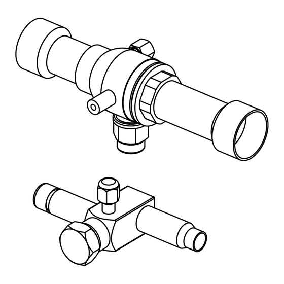
Service Valve Kit
Odyssey Split System Cooling and Heat Pump
6 to 25 Ton Units
BAYVALV020*: Used with TTA060**A, TTA072**A, TTA076**A,
TTA090**A, TTA101**A, TTA120**A, TTA101**C, TTA120**C,
TWA060**A, TWA072**A, TWA101**A, TWA120**A
BAYVALV021*: Used with TWA076**A, TWA090**A
BAYVALV022*: Used with TTA060**D, TTA072**D, TTA076**D,
TTA090**D, TTA101**D, TTA120**D, TWA060**D, TWA072**D,
TWA076**D, TWA090**D, TWA101**D, TWA120**D
BAYVALV023*: Used with TTA126**D, TTA150**D
BAYVALV024*: Used with TTA156**D, TTA180**D, TTA201**D,
TTA240**D
BAYVALV025*: Used with TWA156**D, TWA180**D, TWA201**D,
TWA240**D
BAYVALV026*: Used with TTA156**C, TTA180**C, TTA201**C,
TTA240**C
BAYVALV027*: Used with TTA251**C, TTA300**C
Only qualified personnel should install and service the equipment. The installation, starting up, and servicing of heating, ventilating, and air-conditioning equipment
can be hazardous and requires specific knowledge and training. Improperly installed, adjusted or altered equipment by an unqualified person could result in death or
serious injury. When working on the equipment, observe all precautions in the literature and on the tags, stickers, and labels that are attached to the equipment.
August 2024
SAFETY WARNING
ACC-SVN213C-EN
Advertisement
Table of Contents

Related Manuals for Trane BAYVALV020 Series


Summary of Contents for Trane BAYVALV020 Series
- Page 1 Installation Guide Service Valve Kit Odyssey Split System Cooling and Heat Pump 6 to 25 Ton Units BAYVALV020*: Used with TTA060**A, TTA072**A, TTA076**A, TTA090**A, TTA101**A, TTA120**A, TTA101**C, TTA120**C, TWA060**A, TWA072**A, TWA101**A, TWA120**A BAYVALV021*: Used with TWA076**A, TWA090**A BAYVALV022*: Used with TTA060**D, TTA072**D, TTA076**D, TTA090**D, TTA101**D, TTA120**D, TWA060**D, TWA072**D, TWA076**D, TWA090**D, TWA101**D, TWA120**D BAYVALV023*: Used with TTA126**D, TTA150**D...
-
Page 2: Warnings, Cautions, And Notices
(HCFCs). Not all refrigerants containing these compounds bump cap, fall protection, electrical PPE and arc have the same potential impact to the environment. Trane flash clothing). ALWAYS refer to appropriate advocates the responsible handling of all refrigerants. -
Page 3: Revision History
This document and the information in it are the property of regulations. Trane, and may not be used or reproduced in whole or in part without written permission. Trane reserves the right to revise this publication at any time, and to make changes to... -
Page 4: Pre-Installation
Pre-Installation General Operation and Installation Table 1. Service valve kit unit selection chart BAYVALV020* BAYVALV021* BAYVALV022* BAYVALV023* BAYVALV024* BAYVALV025* BAYVALV026* BAYVALV027* TTA060**A TWA076**A TTA060**D TTA126**D TTA156**D TWA156**D TTA156**C TTA251**C TTA072**A TWA090**A TTA072**D TTA150**D TTA180**D TWA180**D TTA180**C TTA300**C TTA076**A TTA076**D TTA201**D TWA201**D TTA201**C TTA090**A... - Page 5 Pre-Installation Figure 1. Service valve kit shipping list Table 2. Service valve kit shipping list Assembly Description Number Suction Valve; Ball Suction Valve; Ball (dual circuit kits only) Liquid Valve; Ball Liquid Valve; Ball (dual circuit kits only) Screw; #10-16 X .50 Sh Met Literature;...
-
Page 6: Installation
For variable frequency drives or local regulations. or other energy storing components provided by Trane or others, refer to the appropriate manufacturer’s literature for allowable waiting periods for discharge of capacitors. Verify with a CAT III or IV... - Page 7 Installation steel wool at the location you plan to cut and install scraped or reamed with a pointed tool to remove the “T” coupling. When cutting the tubing always any sharp burr in the end of the tube. use a tube cutter. c.
- Page 8 Installation Figure 5. Example placement for service valves in dual circuit 5-12 ton units Installation in Condensing Unit WARNING Explosion Hazard! 1. Remove plugs from the tubing ends of the service valves Failure to follow these instructions could result in death or serious injury or equipment or property-only 2.
- Page 9 Installation WARNING Explosion Hazard and Deadly Gases! Failure to follow all proper safe refrigerant handling practices could result in death or serious injury. Never solder, braze or weld on refrigerant lines or any unit components that are above atmospheric pressure or where refrigerant may be present. Always remove refrigerant by following the guidelines established by the EPA Federal Clean Air Act or other state or local codes as appropriate.
- Page 10 Notes ACC-SVN213C-EN...
- Page 11 Notes ACC-SVN213C-EN...
- Page 12 For more information, please visit trane.com or americanstandardair.com. Trane and American Standard have a policy of continuous product and product data improvement and reserve the right to change design and specifications without notice. We are committed to using environmentally conscious print practices.
Need help?
Do you have a question about the BAYVALV020 Series and is the answer not in the manual?
Questions and answers