Trane Tracer MP503 Installation, Operation And Maintenance Manual
Input/output module
Hide thumbs
Also See for Tracer MP503:
- Installation and operation manual (46 pages) ,
- Manual (8 pages)
Table of Contents
Advertisement
Quick Links
Installation, Operation, and Maintenance
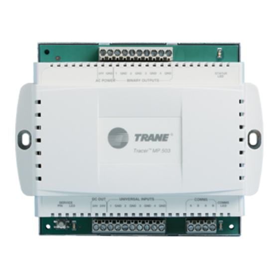
Tracer® MP503 Input/Output Module
Only qualified personnel should install and service the equipment. The installation, starting up, and servicing of
heating, ventilating, and air-conditioning equipment can be hazardous and requires specific knowledge and training.
Improperly installed, adjusted or altered equipment by an unqualified person could result in death or serious injury.
When working on the equipment, observe all precautions in the literature and on the tags, stickers, and labels that are
attached to the equipment.
April 2020
SAFETY WARNING
CNT-SVX09E-EN
Advertisement
Table of Contents
Troubleshooting

Related Manuals for Trane Tracer MP503


Summary of Contents for Trane Tracer MP503
- Page 1 Installation, Operation, and Maintenance Tracer® MP503 Input/Output Module SAFETY WARNING Only qualified personnel should install and service the equipment. The installation, starting up, and servicing of heating, ventilating, and air-conditioning equipment can be hazardous and requires specific knowledge and training. Improperly installed, adjusted or altered equipment by an unqualified person could result in death or serious injury.
- Page 2 Copyright This document and the information in it are the property of Trane, and may not be used or reproduced in whole or in part without written permission. Trane reserves the right to revise this publication at any time, and to make changes to its content without obligation to notify any person of such revision or change.
-
Page 3: Table Of Contents
Table of Contents Overview and Specifications ........5 Product Description . - Page 4 Table of Contents Status Indicators ..........20 MP503 Circuit Board .
-
Page 5: Overview And Specifications
Overview and Specifications This guide provides installation and configuration information for the Tracer™ MP503 input/output (I/O) module, as well as a description of its operations. The overview includes a product description, specifications, and descriptions of additional components needed in some MP503 applications. Product Description The MP503 I/O module is a field-installed device used to monitor inputs and control binary outputs. -
Page 6: Power
Overview and Specifications Power The transformer must meet the following minimum requirements for the controller and its output devices: • 19–30 Vac (24 Vac nominal) • 50/60 Hz • 9 VA and 12 VA maximum per binary output utilized Agency Listing/Compliance CE—Immunity: EMC Directive 89/336/EEC EN 50090-2-2:1996... - Page 7 Overview and Specifications Figure 1. MP503 plastic cover model dimensions and clearances 1 in. (25 mm) 4 in. 4 in. (102 mm) (102 mm) 4 in. (102 mm) 6.31 in. 5.625 in. 6.875 in. (160 mm) (143 mm) (175 mm) 5.375 in.
-
Page 8: General Wiring Information
• All wiring must comply with the National Electrical Code™ (NEC) and local codes. • Use only 18 AWG twisted-pair wire with stranded, tinned-copper conductors (Trane recommends shielded wire). • Binary output wiring must not exceed 1000 ft (300 m). -
Page 9: Communication Link Wiring And Addressing
General Wiring Information Figure 3. Connecting ac power wires to the module 24 Vac transformer Line voltage Use a UL-listed Class 2 power transformer supplying a nominal 24 Vac (20–30 Vac). The transformer must be sized to provide adequate power to the MP503 (10 VA) and to the output devices [including relays], to a maximum of 12 VA per output utilized. -
Page 10: Mounting The Module
Location recommendations • Operating environment requirements • Mounting recommendations Location Recommendations Trane recommends locating the MP503: • Near the controlled equipment to reduce wiring costs • Where it is easily accessible for service personnel • Where public access is restricted to minimize the possibility of tampering or vandalism... -
Page 11: Applications For The Mp503
24 Vac with closed contacts. Thermistor Inputs Thermistor inputs are used to measure temperature. They must be Trane 10kW (at 25°C) thermistors. Any Trane zone temperature sensor can be connected to the MP503; however, the module will not recognize the setpoint thumbwheel or fan speed switch that appears on some sensors. -
Page 12: Outputs
Applications for the MP503 Outputs The binary outputs are Form A single-pole, single-throw (SPST) relay outputs. These relays switch 24 Vac and are not dry contacts. Important: A pilot relay is required for any application requiring dry contacts. Relays connected to the binary outputs on the module cannot exceed 12 VA or 0.5 A current draw at 24 Vac. -
Page 13: Network Variable Bindings
Network Variable Bindings The LonTalk communication protocol allows data to be shared between devices (either as stand- alone or with a BAS) on a LonTalk network as is referred to as peer-to-peer communication. An example of peer-to-peer communication would be when two or more devices are serving the same space, share data (such as a temperature reading) without having to pass the data through a BAS. -
Page 14: Receiving Data
A network variable input (nvi) receives data from other devices on the LonTalk network. Network variable inputs (including their SNVTs) that are commonly used in MP503 bindings are shown in Table 1 Table 1. Tracer MP503 network variable inputs Variable Name Data Type Description... - Page 15 Network Variable Bindings Table 2. Tracer MP503 network variable outputs (continued) Variable name Data type Description nvoBIP1Status SNVT_switch Universal Input 1 Status Output: • Indicates the value of universal input 1 if it is configured as binary. • If universal input 1 is not configured as binary, this output is invalid.
-
Page 16: Examples Of Network Variable Bindings
Network Variable Bindings Table 2. Tracer MP503 network variable outputs (continued) Variable name Data type Description nvoVolts4 SNVT_volt Universal Input 4 Status Output: • Indicates the value of universal input 4 if it is configured as 0–10 Vdc. • If universal input 4 is not configured as 0–10 Vdc, this output is -3276.8. -
Page 17: Display
Figure 7. LonTalk network for example 2 Tracer MP581 #2 Tracer MP581 #1 with operator display with operator display Tracer MP503 ® Additional LonTalk LonTalk link devices Use the Rover service tool to create bindings. (Refer to the Rover Operation and Programming Guide (EMTX-SVX01). -
Page 18: Example 3: Control A Binary Output On The Mp503 From A Mp581
Bind an nvo on the MP581 to an nvi on the MP503 so the AHU and exhaust fan run together. Figure 8 shows the LonTalk network for this example. Figure 8. LonTalk network for example 3 Tracer MP581 with operator display Tracer MP503 ® Additional LonTalk LonTalk link devices CNT-SVX09E-EN... -
Page 19: Mp581
Figure 9 shows the LonTalk network for this example. Figure 9. LonTalk network for example 4 Tracer MP581 with operator display Tracer MP503 ® Additional LonTalk LonTalk link devices Use the Rover service tool to create bindings (refer to the Rover Operation and Programming Guide (EMTX-SVX01). -
Page 20: Status Indicators
MP503 Circuit Board Figure 10 shows the location of the Service Pin button, the Neuron ID label, and LEDs. Figure 10. Tracer MP503 I/O module circuit board Binary output 1 LED (green) Binary output 2 LED (green) Binary output 3 LED (green) -
Page 21: Interpreting Leds
Interpreting LEDs Red Service LED The red Service LED indicates whether the module is capable of operating normally (refer to Table Table 7. Red Service LED LED Activity Explanation LED is off continuously The module is operating normally. when power is applied to the module. -
Page 22: Binary Output Leds (4 Green)
Status Indicators Binary Output LEDs (4 Green) Four (4) green LEDs on the MP503 circuit board indicate the status of the four binary outputs (refer Table 10). Table 10. Binary output LEDs LED Number Binary Output CR10 CR11 (a) Each binary output LED reflects the status of the output relay on the circuit board. It may or may not reflect the status of the equipment the binary output is controlling. -
Page 23: Troubleshooting
Troubleshooting Troubleshooting This section provides information about general troubleshooting steps to perform if there is a problem with the operation of the equipment controlled by the MP503. Important: Troubleshooting that involves accessing live electrical devices must be conducted only by a properly trained and authorized electrician or trained technician. When encountering operational problems with the MP503, first perform the initial troubleshooting in the following section, “Initial... -
Page 24: Troubleshooting Binary Output (Relay Output)
Troubleshooting Binary Output (Relay Output) If a binary output (relay output) is not turning on the equipment wired to it, then follow the troubleshooting steps in Table 14. Perform the steps in the order they are listed. The troubleshooting steps assume the equipment connected to the binary output is OFF when it is believed to be ON and vice versa when it should be OFF. -
Page 25: Troubleshooting Universal Input
Troubleshooting Troubleshooting Universal Input If a universal input value appears incorrect, follow the troubleshooting steps in Table 16 Table Table 16. Troubleshooting universal inputs using the device plug-in Step Number Action Probable Cause Connect the Rover service tool to the LonTalk communication link, start the Rover service tool, and select the MP503 from the Active Group Tree. - Page 26 Troubleshooting Figure 11. Voltage measured across terminals vs. temperature Temperature (°F) Temperature (°C) Note: The correct region is shown in gray. A range of measurements is shown due to the variability of reference voltages the thermistors. Table 19. Universal input troubleshooting with a binary input Step Number Action Probable Cause...
- Page 27 Troubleshooting Figure 12. Voltage measured across terminals vs. input current Current (mA) Table 21. Universal input troubleshooting with a 0–10 Vdc input Step Number Action Probable Cause After following the steps in Table 17, p. 25, disconnect the sensor wires from the input terminals. Use the volt meter (set to read dc voltage) to measure the voltage across the terminals for the Circuit board Step 1...
-
Page 28: Index
Index Numerics 0–10 Vdc inputs Rover service tool 23 Troubleshooting 25 0–20 mA inputs Status Indicators Troubleshooting 25 diagnostics 22 interpreting LEDs 21 Agency Listing/Compliance 6 MP503 circuit board 20 Applications service pin button 20 inputs 11 outputs 12 Thermistor inputs Troubleshooting 25 Binary inputs Troubleshooting... - Page 32 For more information, please visit trane.com or tranetechnologies.com. Trane has a policy of continuous product and product data improvement and reserves the right to change design and specifications without notice. We are committed to using environmentally conscious print practices.
Need help?
Do you have a question about the Tracer MP503 and is the answer not in the manual?
Questions and answers