Dimplex BF33STP Service Manual
Hide thumbs
Also See for BF33STP:
- Installation manual (42 pages) ,
- Parts and service instructions (27 pages) ,
- Practical user's manual (15 pages)
Table of Contents
Advertisement
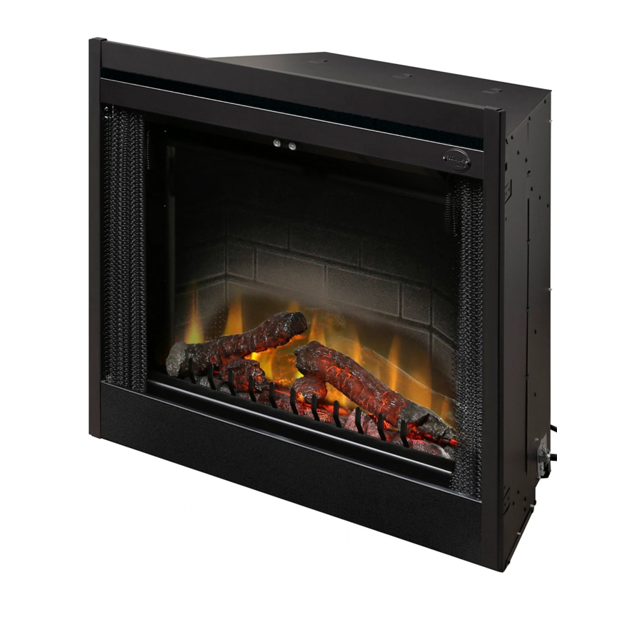
DXP Model Shown
IMPORTANT SAFETY INFORMATION: Always read this manual first before attempting to service this
fireplace. For your safety, always comply with all warnings and safety instructions contained in this
manual to prevent personal injury or property damage.
Dimplex North America Limited
1367 Industrial Road Cambridge ON Canada N1R 7G8
1-888-346-7539 www.dimplex.com
In keeping with our policy of continuous product development, we reserve the right to make changes without notice.
© 2011 Dimplex North America Limited
Service Manual
Model Number
BF33STP
BF33DXP
BF39STP
BF39DXP
BF45DXP
UL Part Number
6901811400
6901811500
6901811600
6901811700
6901811900
REV
PCN
DATE
00
-
3-AUG-11
7400380000R00
Advertisement
Table of Contents

Related Manuals for Dimplex BF33STP


Summary of Contents for Dimplex BF33STP
- Page 1 Dimplex North America Limited 1367 Industrial Road Cambridge ON Canada N1R 7G8 DATE 1-888-346-7539 www.dimplex.com 3-AUG-11 In keeping with our policy of continuous product development, we reserve the right to make changes without notice. © 2011 Dimplex North America Limited 7400380000R00...
-
Page 2: Table Of Contents
NOTE: Procedures and techniques that are considered important enough to emphasize. CAUTION: Procedures and techniques which, if not carefully followed, will result in damage to the equipment. WARNINg: Procedures and techniques which, if not carefully followed, will expose the user to the risk of fire, serious injury, or death. www.dimplex.com... -
Page 3: Operation
The heater will re-activate once the heater has cooled. The overheat cutout will be triggered if the filter is dirty. CAUTION: If you need to continuously reset the heater, disconnect power and call Dimplex customer service at 1-888-DIMPLEX (1-888-346-7539). -
Page 4: Battery Replacement
Strip advice in your area. 8, 9, and 10 sequentially. To disengage, press 8, 9 and 10 sequentially again. The Indicator icon will be displayed Battery when enabled. Cover 7 . RF Code Function and Change Procedure - In www.dimplex.com... - Page 5 the event that the Wall Switch Remote Control does not the “6 hr” icon display. After 6 hours have passed and all work properly with the receiver due to interference from functions are turned off, “6 hr” will flash until any button is additional wireless signals, this function will allow the RF pressed.
-
Page 6: Exploded Parts Diagram
EXPLODED PARTS DIAgRAM CATALOgUE NUMBER BF33STP BF33DXP BF39STP BF39DXP BF45DXP UL PART NUMBER 6901811400 6901811500 6901811600 6901811700 6901811900 REPLACEMENT PART 1. LOG SET 0438200300RP 0439230100RP 0438550200RP 0439070100RP 2. REFLECTOR ROD 5900081000RP 5900080900RP 3. GROMMET 8500000600RP 4. FLICKER MOTOR 6901811200RP 6. BLOWER MOTOR 5300160100RP 7. -
Page 7: Wiring Diagram - Stp Models
WIRINg DIAgRAM - STP MODELS... -
Page 8: Wiring Diagram - Dxp Models
WIRINg DIAgRAM - DXP MODELS www.dimplex.com... -
Page 9: Switch Replacement
SWITCh REPLACEMENT - Main On/Off Figure 6 Power; Purifier/Heat; Mode Selector Tools required: Phillips head screwdriver Flat head screwdriver NOTE: Depending on the Modification Level (MOD.) of your fireplace you will have at least two (or a variation) of these types of switches: MAIN ON/OFF POWER; PURI- FIRE/HEAT;... -
Page 10: Led Driver Board Replacement - Dxp Models Only
Open the steel curtains (remove glass doors if appli- cable). Remove the 2 screws from the log set retaining plate along the front of the log set and remove the retaining Remove the 2 screws from the log set retaining plate www.dimplex.com... -
Page 11: Blower / Motor Replacement
plate. edge first then push the backside of the log-set down until the rear tab snaps under the back partially reflective glass Pull the rear edge of the log set forward by grasping ledge and the logs are resting against the partially reflective the ember bed by the sides (handle the log set only by glass. -
Page 12: Removable From Wall
WARNINg: Disconnect circuit power before attempt- of skin. ing any maintenance or cleaning to reduce the risk of WARNINg: Disconnect circuit power before attempt- electric shock or damage to persons. www.dimplex.com... -
Page 13: Element Replacement
ing any maintenance or cleaning to reduce the risk of Disconnect the log set LED wire harness from unit. electric shock or damage to persons. (DXP MODELS ONLY) Remove unit from installed wall (remove trim surround, Release the steel curtains from the side panels by if applicable). -
Page 14: Voltage Selector Switch Replacement
Remove the voltage selector wire connections from the switch noting their original locations. NOTE: Using a flat head screwdriver gently pry be- www.dimplex.com... -
Page 15: Bfrc-Kit Remote Control Receiver Installation/Replacement
BFRC-kIT REMOTE CONTROL in the fireplace as per the instructions included in the remote packaging. RECEIVER INSTALLATION/ WRCPF-kIT WALL CONTROLLER REPLACEMENT INSTALLATION/REPLACEMENT Tools Required: Philips head screwdriver WARNINg: If the fireplace was operating prior to Tools Required: Philips head screwdriver servicing allow at least 10 minutes for light bulbs and WARNINg: If the fireplace was operating prior to heating elements to cool off to avoid accidental burning... -
Page 16: Bf Plug Kit Replacement (Bfpluge)
Plug the fireplace back into the outlet for power. If fireplace has a BFRC-KIT (remote control kit) used to operate the unit, the remote control may need to be re-synchronized to the fireplace once power has been restored to the fireplace. www.dimplex.com... -
Page 17: Assembly Component Pictures
ASSEMBLY COMPONENT PICTURES Left Element Connections Right Element and Blower Connections Elements, Blower and Voltage Selector high Temperature Cutout Connections Exterior View of Voltage Selector Switch and Interior Bottom View of Voltage Selector Over Temperature Light Switch and Over Temperature Light... - Page 18 LED Driver Board Uninstalled Flicker Motor and Terminal block Rear View Light Panel/harness Flicker Rod and Flicker Motor Attachment Manual Controls Manual Controls Interior Side View with Remote Control Bracket Removed “Dummy Plug” (Factory In- stalled) No Remote Operation www.dimplex.com...
-
Page 19: Troubleshooting Guide
TROUBLEShOOTINg gUIDE PROBLEM CAUSE SOLUTION general Circuit breaker trips or fuse Short in unit wiring. Trace wiring in unit. blows when unit is turned on Improper circuit current rating Verify unit is installed on a dedicated 15 amp circuit. Unit turns on or off by itself Remote Control has a similar frequency Replace Remote Control to other remotes in the area. - Page 20 Grinding or excessive noise with Moving flicker rod hitting or rubbing Ensure rod is straight and mounted properly in the the heater off against internal components bracket, spinning freely away from other components. Replace if necessary. Defective flicker motor Replace flicker motor www.dimplex.com...
Need help?
Do you have a question about the BF33STP and is the answer not in the manual?
Questions and answers