Advertisement
Table of Contents
- 1 Table of Contents
- 2 Operation
- 3 Replacement Parts List
- 4 Exploded Parts Diagram and Parts List
- 5 Wiring Diagram
- 6 Light Bulb Replacement
- 7 Mirror Replacement
- 8 Switch Replacement
- 9 Flicker Motor/Flicker Rod Replacement
- 10 Heater Assembly/Cutout Replacement
- 11 Remote Receiver Board Replacement
- 12 Power Cord Replacement
- Download this manual
See also:
Owner's Manual
Service Manual
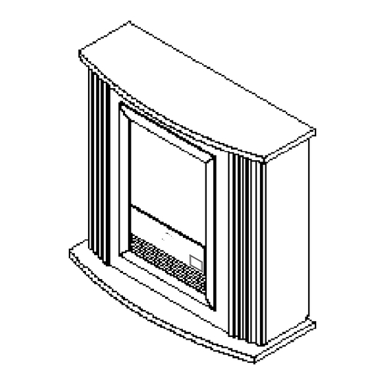
Mozart Fireplace
Model Numbers:
CFP3913
Dimplex North America Limited
1367 Industrial Road
Cambridge ON Canada N1R 7G8
1-888-346-7539
www.dimplex.com
In keeping with our policy of continuous product development, we reserve the right to make changes without notice.
REV
PCN
DATE
00
11637
Sep 23, 09
7400270000rev00
Advertisement
Table of Contents

Related Manuals for Dimplex CFP3913


Summary of Contents for Dimplex CFP3913
- Page 1 Model Numbers: CFP3913 DATE 11637 Sep 23, 09 Dimplex North America Limited 1367 Industrial Road Cambridge ON Canada N1R 7G8 1-888-346-7539 www.dimplex.com In keeping with our policy of continuous product development, we reserve the right to make changes without notice.
-
Page 2: Table Of Contents
Table Of Contents Operation ........... . . Page 3 Exploded Parts Diagram and Parts List. -
Page 3: Operation
CAUTION: If you need to continuously reset the heater, NOTE: This switch must be in the ON (I) position for unplug the unit and call Dimplex North America Limited at heater to operate with or without heat. 1-888-346-7539 for technical support. -
Page 4: Exploded Parts Diagram And Parts List
Exploded Parts Diagram Replacement Parts List CFP3913 Part Number 6904890100 Replacement Part: 1. Log set......0439290100RP 8. -
Page 5: Wiring Diagram
Wiring Diagram Remote Receiver Board Flicker Motor Low Heat Switch High Heat Switch 3 Position On/Off Switch Cutout Cord Set Power Terminal Block Heater Assembly Circuitry Terminal Block Wire # Colour Yellow Black Grey Blue Blue Grey Grey Black Blue Grey Blue Blue... -
Page 6: Light Bulb Replacement
Light Bulb Replacement Mirror Replacement Allow at least five (5) minutes for light bulbs to cool before If the fireplace was operating prior to servicing allow at least touching bulbs to avoid accidental burning of skin. five (5) minutes for light bulbs and heating element to cool off to avoid accidental burning of skin. -
Page 7: Switch Replacement
Figure 5 Figure 7 Trim Screws (2) Screws to Mirror Retaining remove (12) Bracket Mirror Log Set Do not remove these 2 screws Switch Replacement If the fireplace was operating prior to servicing allow at least five (5) minutes for light bulbs and heating element to cool off to avoid accidental burning of skin. -
Page 8: Flicker Motor/Flicker Rod Replacement
the firebox. Figure 9 11. Pull the Flicker Rod to the far right, towards the Flicker Retainer Clip - Piggy-back connections Motor, then bend it gently enough to clear the bracket on the left (Figure 8). Figure 8 Flicker Rod Flicker Motor A - 3 Position On/Off Switch B - Low Heat Switch... - Page 9 7. Remove the seven (7) screws that attach the Top Panel Figure 11 to the firebox. There are: two (2) Phillips screws along each side at the top edge of the firebox; and three (3) Phillips screws at the back of the firebox, along the top edge (Figure 6, page 7).
-
Page 10: Heater Assembly/Cutout Replacement
23. Turn firebox on it’s back. Mounting Bracket will separate here as well); two (2) screws along each side; two (2) screws under the front 24. Referring to Figure 11 (page 9), reconnect the single edge of the firebox; and one (1) screw which connects to black wire from the Flicker Motor to the upper, right the Heater Assembly (Figure 10, page 9). -
Page 11: Remote Receiver Board Replacement
vii) From within the firebox, disconnect the two (2) orange Figure 14 wires that connect to the back of the Low Heat Switch Cutout Screw and the 3 Position On/Off Switch (there are four (4) wires Cutout and four (4) clips in total, but the wires are paired into two (2) piggy-back connections - one (1) per switch) Access to switches (Figure 13). -
Page 12: Power Cord Replacement
Mirror Retaining Bracket in place (Figure 7, page 7) and to be inserted through the sheet metal of the chassis remove. from the outside). 9. Slide Mirror up from within the firebox to remove. 21. Reconnect the three (3) wire clips from step 18 following Figure 15 as a guide. - Page 13 screwdriver, release the two (2) black wires from the Figure 17 Terminal Block (turn the screws of the Terminal Block Terminal Block counter-clockwise) which lead from the Power Cord. Take note of their original positions. Wire with smooth edges leads to Black 8.
Need help?
Do you have a question about the CFP3913 and is the answer not in the manual?
Questions and answers