Advertisement
Quick Links
DISCOVERY DUO
DISCOVERY DUO/AM
Dual-Technology Microwave/PIR Intrusion Detectors
1. FEATURES
Cylindrical optics improves detection and false alarm immunity.
True Motion Recognition™ (TMR) algorithm (patented)
distin- guishes between the true motion of a human body and
other disturbances which invariably cause false alarms
DRO-stabilized MW microstrip technology (patented)
MW Motion Simulator simulates the effect of a human body
moving in the MW field (for MW self-test - patent pending)
Range control for adjusting the MW coverage
Integral swivel bracket for wall or ceiling installation
Sealed chamber protects the pyroelectric element from
insects.
PIR self-test by applying a short heat pulse (DISCOVERY
DUO/AM only)
2. SPECIFICATIONS
Input Voltage: 9 to 16 VDC
Current Drain: About 28 mA @ 12 VDC
PIR SECTION
Detector: Low noise dual-element pyroelectric sensor
Tripping Indication: LED flashes green for up to 5 seconds
Motion Event Verification Counter: Selectable, 1 or 2 events
Lens Data (No. 105DH - see Figure 2)
No. of Beams: 36 in two layers (curtain beams in bottom layer)
Max. Coverage: 12 x 12 m (40 x 40 ft) / 90° field of view
Vertical Adjustment: FAR and NEAR, by sliding the circuit
board along a two-position scale.
MW SECTION
Oscillator: Microstrip DRO-stabilized Doppler module
Frequency: 10.525 GHz (U.S.A. only) or 2.45 GHz (Europe)
Detection Range: Adjustable from 25% to 100% (3 m to 12 m)
Tripping Indication: LED glows green for up to 5 seconds
ALARM, TAMPER & TROUBLE DATA
Alarm Indication: LED glows red for 1.3 to 5 seconds if both
detectors trip
Relay Contacts: N.C., rated at 0.1 A resistive / 30 VDC; 18
resistor in series with contacts
Alarm Duration: 1.3 to 5 seconds
Tamper Switch: N.C., rated at 50 mA resistive / 30 VDC
Trouble Output: Open collector, 100 mA max., with 18
in series and 47 k
pull-up (see Figure 11)
Masking Detection Delay (/AM version only): About 60 seconds
Trouble/ Masking Indication: LED alternately flashes green and
red and TRB output pulls LOW until the detector is reset.
3. INSTALLATION
3.1 Installation Hints
To minimize false alarms:
Do not aim at heat sources
DE1835 DISCOVERY DUO / DISCOVERY DUO AM Installation Instructions
resistor
Mount on solid, stable surfaces
Programmable motion event
counter (1 or 2 events)
Simple-to-use, two-position
vertical adjustment
TEST input to enable/disable
the walk test LED remotely
(per new European standard)
Open collector trouble output
Anti-masking protection
(DISCOVERY DUO/AM only)
White light protection.
MOUNTING
Height: Up to 3.6 m (12 ft)
Room Size: 8 - 12 m (24 -
40 ft) in the "FAR" position;
2 - 8 m (6 - 24 ft) in the NEAR
position.
Bracket
Adjustment:
downward, 20° left and right.
Installation Options: Surface or
corner (without bracket); surface
or ceiling (with bracket)
ENVIRONMENTAL
RFI Protection: >30 V/m up to
1000 MHz.
Operating Temperatures: -10°C
to 50°C (14°F to 122°F).
Storage Temperatures: -20°C to
60°C (-4°F to 140°F).
Standards: Complies with Part 15 of the FCC Rules.
This device is designed to comply with the essential requirements
and provisions of Directive 1999/5/EC of the European Parliament
and of the Council of 9 March 1999 on radio and
telecommunications terminal equipment.
2.45 GHz has no restriction in any EU member state.
To comply with the Canadian standard RSS-210, this device
must be operated indoors only to provide maximum shielding
and to prevent interference to licensed services.
PHYSICAL
Size (H x W x D): 117 x 65 x 47 mm (4-5/8 x 2-9/16 x 1-7/8 in.).
Weight: 109 g (3.85 oz) w/o bracket, 124 g (4.4 oz) with bracket.
PATENTS
U.S. Patents 5,237,330 and 5,693,943 (other patents pending)
Do not expose to air drafts
Installation Instructions
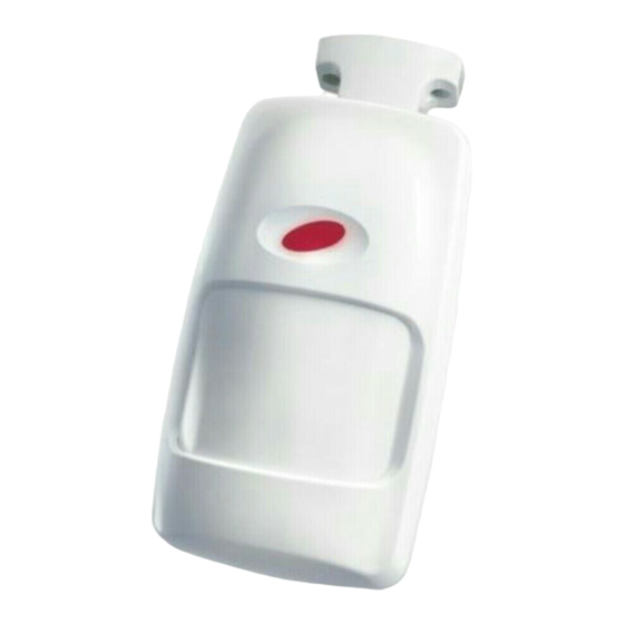
Figure 1. General View
20°
Figure 2. Coverage Pattern
Do not install outdoors
1
Advertisement

Related Manuals for Visonic DISCOVERY DUO


Summary of Contents for Visonic DISCOVERY DUO
- Page 1 U.S. Patents 5,237,330 and 5,693,943 (other patents pending) 3. INSTALLATION 3.1 Installation Hints To minimize false alarms: Do not aim at heat sources Mount on solid, stable surfaces Do not expose to air drafts Do not install outdoors DE1835 DISCOVERY DUO / DISCOVERY DUO AM Installation Instructions...
- Page 2 2. Large reflecting objects (especially metals) in the coverage area can distort the microwave detector's coverage pattern. 3. If two DISCOVERY DUO units are installed in the same room or on opposite sides of a shared wall, they should not face each other and must be mounted at least 2 meters apart.
- Page 3 PC board (refer to Figure 5). Two positions supplied to the detector is above 9 Volts with the backup battery as are available - FAR and NEAR. All new DISCOVERY DUO units are the only power source.
- Page 4 If WARRANTY Visonic Limited (the “Manufacturer") warrants this product only (the "Product") to the original purchaser only (the However, if the Manufacturer is held liable, whether directly or indirectly, for any loss or damage arising under this “Purchaser”) against defective workmanship and materials under normal use of the Product for a period of twelve...
Need help?
Do you have a question about the DISCOVERY DUO and is the answer not in the manual?
Questions and answers