Table of Contents
Advertisement
Quick Links
Advertisement
Table of Contents

Related Manuals for Visonic MKP-160


Summary of Contents for Visonic MKP-160
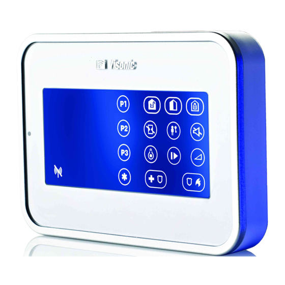
- Page 1 User Guide MKP-160 Keyprox User's Guide...
-
Page 2: Table Of Contents
Partition Selection PANIC: Press both keys disabled DISARM simultaneously for 2 seconds LED (green and red) ARM HOME / QUICK ARM HOME AUX / Enroll MKP-160 / Back to factory / Cancel ARM AWAY / QUICK ARM AWAY current operation LATCHKEY... - Page 3 2.2 Closing Battery Compartment Cover ................3 2.3 Wall Mounting Options ....................4 2.4 Enrolling the MKP-160 ....................9 2.5 Configuring the MKP-160 Parameters ................9 2.6 Enrolling Proximity Tags ...................10 3. USING THE TOUCH SCREEN KEYPROX ..............12 3.1 Arming and Disarming the System ................12 3.2 Initiating Alarms ......................13...
- Page 4 (see keys marked "7" in the "Quick Reference Guide"). The MKP-160 can be wall-mounted using the supplied bracket or be used as a desktop unit. For compliance with various international standards, the MKP-160 is equipped with two tamper switches that can be defined to detect when the cover of the battery compartment is removed or when the unit is removed from its mounting bracket.
- Page 5 Dispose of used battery according to manufacturer's instructions. Figure 1 – Battery Insertion Insert two 1.5V batteries in each slot while ensuring battery polarity. Figure 2 - Battery Cover Mounting (part a) D-303503 MKP-160 User's Guide...
- Page 6 B. DC Power Connection – use supplied cable in addition to batteries C. Wiring channel for wall installation Note: The DC cable is available in specific models The MKP-160 unit mounting options are illustrated in the following drawings. Wall Mounting Figure 4 – Wall Mounting 1.
- Page 7 2 screws A. Hole for DC power source cable installed in wall B. Hole for tamper WARNING! The power source (optional) must be 5 - 12VDC. D-303503 MKP-160 User's Guide...
- Page 8 4. Connect together the power source cable upward to separate the battery and the DC cable connector (supplied). compartment cover from the front cover Note: The DC cable connector is available in specific models C. DC Power Cable Connection D-303503 MKP-160 User's Guide...
- Page 9 6. Align the bracket pins with their DC power connection. respective slots. Note: You can connect the DC cable directly, as shown in the top drawing, or via one of the wiring inlets indicated by the arrows. D-303503 MKP-160 User's Guide...
- Page 10 7. Push the MKP-160 unit downward on the 8. Secure the unit with the screw bracket Figure 5 – Wall Mounting with External DC Cable Desk mount 1. Insert the bracket pins into the corresponding slots. Figure 6 – Desk mount installation...
- Page 11 Configure the MKP-160 Keyprox See section 2.5 means scroll and select Note: If the MKP-160 is already enrolled, you can configure the MKP-160 parameters via the “16.DEFINE ARM ST” main menu. 16.DEFINE ARM ST Enter the main menu in the PowerMax control panel, choose the number of the touch screen keyprox device to configure and follow the configuration instructions for the MKP-160 touch screen keyprox.
- Page 12 LCD keyprox. Options settings: enable (default) and disable. You can enroll proximity tags in the PowerMax control panel either through the MKP-160 touch screen keyprox, as described below, or through the PowerMax control panel, as described in the corresponding section of the control panel's User or Installer Guide.
-
Page 13: Present Prox Tag
) on the MKP-160. The AWAY key and the Present Prox Tag key ( begin to blink Present the proximity tag to the MKP-160 within Tag no : 8 the 5 second timeout period. If the enrollment is successful, the display reads the selected Prox Tag number followed by a box. -
Page 14: System Status
• INSTANT is available only if supported in the PowerMax control panel (refer to the PowerMax Installer Guide). For LATCHKEY activation, press the LATCHKEY key within maximum 8 seconds timeout period after completing the previous step. D-303503 MKP-160 User's Guide... - Page 15 MKP-160 sends the Panic command. When executing a command, the MKP-160's LED ("29" in the "Quick Reference Guide") blinks red once to indicate transmission of the command to the control panel. If the operation is successfully completed, the green LED lights momentarily and a "happy tune" sounds.
- Page 16 System is READY but one or more zones are bypassed. No indication System is READY and all zones are secured. Bypassed ( ) or Open ( ) Zone number Selected PGM or X-10 unit number. Volume level D-303503 MKP-160 User's Guide...
- Page 17 The partition / system has an active trouble status that needs to be reviewed and cleared. AC failure. Communication failure: MKP-160 is out of range of the control panel or did not get an acknowledge signal of a command from the control panel.
-
Page 18: Pgm / X-10 Display
(marked "4" in the "Quick Reference Guide") followed by the key. Note: Zone bypassing on the MKP-160 unit can be operated only if Bypass was enabled via the control panel (see PowerMax Installer Guide). To operate home automation devices, see the table below. -
Page 19: Mute Exit Beeps
Enrollment: Long key press (more than 5 sec.) AUX Function until green LED lights and then release key. Back to Factory: Long key press (more than 7 sec.) to reset the MKP-160 device to factory default settings. Cancels current operation: Short key press Volume control Changes the volume level upon each key press. - Page 20 Europe: EN 300220-1, EN 300220-2, EN300330, EN301489, EN60950, EN50131-1, EN50131-3, EN50131-6. USA: CFR 47 part 15 Canada: RSS 210 RFID Tags: ISO-18000-2 (125 kHz) Grade 2 EN 50131-1 Security Grade EN 50131-1 Environmental Class Class 2 D-303503 MKP-160 User's Guide...
- Page 21 – Connect the device to an outlet on a circuit different from the one which supplies power to the receiver. – Consult the dealer or an experienced radio/TV technician. Changes or modifications not expressly approved by Visonic Ltd. could void the user's authority to operate the equipment.
- Page 22 WARRANTY THE MANUFACTURER SHALL IN NO EVENT BE Visonic Limited (the “Manufacturer") warrants this LIABLE SPECIAL, INDIRECT, product only (the "Product") to the original purchaser INCIDENTAL, CONSEQUENTIAL OR PUNITIVE only (the “Purchaser”) against defective DAMAGES LOSS, DAMAGE, workmanship and materials under normal use of the...
-
Page 23: Instant
VISONIC INC. (U.S.A.) 65 West Dudley Town Road, Bloomfield CT. 06002-1376. Tel.: (860) 243-0833, (800) 223-0020. Fax: (860) 242-8094 VISONIC Ltd. (UK) Unit 6 Madingley Court Chippenham Drive Kingston Milton Keynes Mk10 0Bz. Tel.: (0870) 7300800 Fax: (0870) 7300801. Tel: (0870) 7300800 Fax: (0870) 7300801 Product Support: (0870) 7300830 VISONIC GmbH (D-A-CH) Kirchfeldstr. - Page 24 Additional PowerCode Products for Your Security and Safety Needs: Wireless Wireless Fire Curtain-type Proximity Detector Detector Tags Wireless PIR/ Wireless Pet-immune Outdoor Mirror GSM/GPRS Detector Detector Communicator Wireless Wireless Indoor Outdoor Siren Siren www.visonic.com...
Need help?
Do you have a question about the MKP-160 and is the answer not in the manual?
Questions and answers