Advertisement
Quick Links
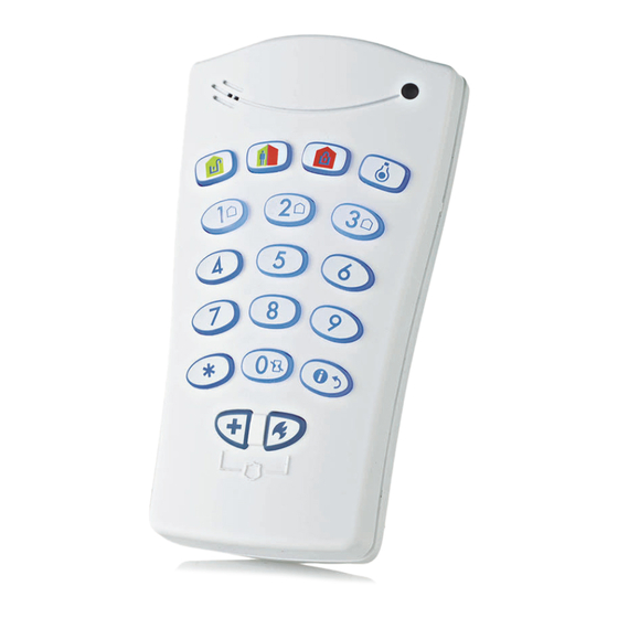
KP-140 PG2/KP-141 PG2
Portable Remote Wireless 2-Way Keypad
1. INTRODUCTION
KP-140 PG2 and KP-141 PG2 are 2-way PowerG wireless keypads for
the PowerMaster family control panels. The KP-141 PG2 is the same
as the KP-140 PG2 but also includes a built-in proximity RFID tag
reader. Both keypads enable most common everyday user functions:
Arm and Disarm the alarm system.
Initiate Emergency, Fire and Panic alarms.
Control X-10 devices and PGM output.
Perform one of the AUX (auxiliary) predefined functions.
Review system Status.
When authorization is required, for example, to arm or disarm the
system, the user can enter his PIN Code via the built-in numerical
keypad or alternatively present a valid proximity tag to the built-in tag
reader (only with KP-141PG2) located at "N" in Figure 1.
In addition, the KP-140 PG2/KP-141 PG2 keypad supports panels
featuring Partitions. Partitioning allows you to have up to three
controllable areas; each partition can be armed and disarmed
independently regardless of the status of the other two partitions by the
same or different users (see buttons marked "E" in Figure 1).
The keypads can be wall mounted using the supplied bracket or be
used as portable units. For compliance with various international
standards, the keypads are equipped with two tamper switches that
can be configured to detect when the cover of the battery compartment
is removed or when the unit is removed from its mounting bracket.
Other features of the KP-140 PG2/KP-141 PG2 keypad include:
Status, alarm memory, trouble and Ready / Not-Ready indications.
Automatic reporting of low battery voltage.
Keypad back lighting.
Exit/entry beeps
Tag reader can also be used to enroll proximity tags into the panel.
Long-life 4-5 years battery life expectancy (for typical use), 3 VDC
lithium battery.
2. INSTALLATION
2.1 Mounting and Battery Replacement
1
2
1.
Drill 2 holes in mounting surface, insert wall anchors and fasten the
bracket with 2 screws.
2.
Place the "Visual Indications" sticker within the frame.
3. Slide the keypad into the bracket.
A. Magnet (activates back tamper when bracket is removed from the wall).
Figure 2 - Mounting
2.2. ENROLLMENT
Refer to the PowerMaster panel's Installer Guide and follow the procedure under the "02:ZONES/DEVICES" option of the Installer Menu a
general description of which is provided in the following flow chart.
Step 1
Enter the Installer menu
Select "ADD NEW
and select "ZONES /
DEVICES"
02.ZONES/DEVICES
ADD NEW DEVICES
MODIFY DEVICES
Means scroll
and select
D-303015
3
A
Step 2
Step 3
Enroll the device or Enter
DEVICE" Option
the device ID
See Note [1]
ENROLL NOW or
ENTR ID:XXX-XXXX
B
A
C
D
E
F
G
H
I
J
K
A. ARM HOME
H. AUX / ENROLLMENT
B. ARM AWAY
I. EMERGENCY
C. DISARM
J. FIRE
D. X-10 / PGM
K. PANIC
E. PARTITION SELECTION
L. BUZZER INDICATOR
F. ARM INSTANT
M. LED INDICATOR
G. STATUS / ESCAPE
N. TAG READER
Figure 1 - External View
1.
Slide out the cover.
2. Replace the battery (verify proper polarity) and close the cover.
A. Battery compartment tamper switch
Figure 3 - Battery Replacement
Step 4
Select the desired Zone Number
K06: Keypad
ID No. 370-XXXX
User's Guide
L
M
N
ALARM
ALARM
ALARM
A
1
2
Configure Location, Zon
K06.LOCATION
K06.SET CHIME
K06.DEV SETTINGS
Step 5
Paramete
K06.Z
1
Advertisement

Related Manuals for Visonic KP-140 PG2


Summary of Contents for Visonic KP-140 PG2
- Page 1 KP-140 PG2 and KP-141 PG2 are 2-way PowerG wireless keypads for the PowerMaster family control panels. The KP-141 PG2 is the same as the KP-140 PG2 but also includes a built-in proximity RFID tag reader. Both keypads enable most common everyday user functions: ...
-
Page 2: Arming And Disarming The System
[2] Select the "Device Settings" option and refer to section 2.3 to configure the keypad parameters. 2.3. Configuring the Keypad Parameters DEVICE SETTINGS Enter the menu and follow the configuration instructions for the KP-140 PG2/KP-141 PG2 keypad as described in the following table. Option Configuration Instructions TAMPERS Here you determine which of the two tampers (i.e. -
Page 3: Initiating Alarms
Momentary RED Sad (failure) beep To identify the reason, press the button to retrieve the Status indication - refer to section No communication: Control None None 3.6 for further information. panel does not respond. D-303015 KP-140 PG2, KP-141 PG2 Installation Instructions... - Page 4 VISONIC GmbH (D-A-CH): KIRCHFELDSTR. 118, D-40215 DÜSSELDORF, TEL.: +49 (0)211 600696-0, FAX: +49 (0)211 600696-19 VISONIC IBERICA: ISLA DE PALMA, 32 NAVE 7, POLÍGONO INDUSTRIAL NORTE, 28700 SAN SEBASTIÁN DE LOS REYES, (MADRID), ESPAÑA. TEL (34) 91659-3120, FAX (34) 91663-8468. www.visonic-iberica.es INTERNET: www.visonic.com...
Need help?
Do you have a question about the KP-140 PG2 and is the answer not in the manual?
Questions and answers