Table of Contents
Advertisement
Quick Links
MKP-150/151/152
2-Way Wireless Keypad
1. INTRODUCTION
NOTE: RELEVANT TO POWERMAX+ VERSION B AND ABOVE
The MKP-150/151(different color) and MKP-152 operate using two-way
encrypted coded transmission and provides aural and visual indications.
For
each
PowerMax+,
PowerMax
PowermaxExpress control panel, a maximum of two MKP-150/151/152
keypad devices may be enrolled.
The
MKP-150/151/152
includes
Partitioning allows you to have up to three independently controllable
areas with different user codes assigned to each partition or one user
code assigned to up to three partitions. A partition can be armed or
disarmed regardless of the status of the other partitions within the
system.
Note: The Partition feature appears only after Partitioning is enabled
via the control panel.
The MKP-150/151/152 may be operated either by AC power supply
or by battery power. If AC power is used, the device operates
continuously and the system status is constantly updated. If powered
by batteries, the keypad enters sleep mode 15 sec after last key
press. The keypad immediately becomes operational again upon
pressing of any key.
Note: In the event of an AC power failure, the MKP-150/151/152
operates on batteries as described above.
The device enables the user to arm/disarm the alarm system, to initiate
emergency/fire/panic alarms and to turn lighting devices on and off.
The main features of the MKP-150/151/152 are:
Status, alarm memory, and trouble data retrieval from the control panel.
Automatic reporting to the control panel of low battery voltage, AC
failure, tamper.
Visual indications by red/green/amber LED and LCD display.
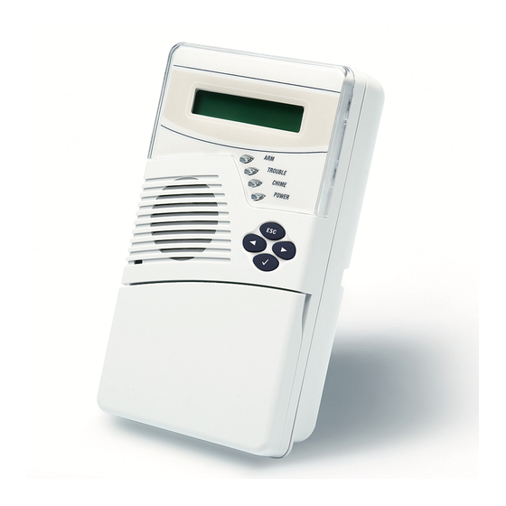
SPEAKER
MICROPHONE
DE2462U MKP-150/151/152 User Guide
Pro,
PowerMaxComplete,
an
optional
partition
feature.
AWAY
PLAY MESSAGE
VOLUME DOWN /
CHIME ON/OFF
MUTE SPEAKER
NO ENTRY DELAY
EMERGENCY
Figure 1a: External View – MKP-150/151
Keypad and LCD backlighting activation.
Light dim / brightness
Various audible signals sounded by the speaker in response to
specific actions.
Automatic supervision messages.
Diagnostic test of the control panel.
Two long-life 3 Volt Lithium batteries.
Wall mounting.
Friendly programming.
The Power (green) LED lights when operated using AC power. The
Trouble (amber) LED lights if a "trouble" state is currently detected
within the control panel. The Chime (green) LED lights when the chime
function is active. The Arm (red) LED lights when the system is in
armed state (away mode), or flashes (home mode).
A periodic supervision message is transmitted, at regular intervals, from
the MKP-150/151/152 to the control panel. This ensures active
participation of the MKP-150/151/152 in the system.
Operating power is obtained from two 3 Volt Lithium batteries, or by
AC. A weak battery causes a "low battery" message to be sent to the
control panel.
A Screen Saver appears on the display (if enabled by the installer on the
control panel unit) when no key is pressed for more than 30 seconds.
The display reads "POWERMAX" and the LEDs do not light (to prevent
an intruder of knowing the system status). The normal display returns
after pressing the OFF button followed by entering user code (Refresh
by Code) or after pressing any key (Refresh by Key), depending on the
control panel settings of the installer. If Refresh by Key was selected,
the first key press (except for Fire and Emergency) causes the normal
display to return while a second press performs the key function. In the
case of the Fire and Emergency keys, the first key press causes the
normal display to return and also performs the Fire/Emergency function.
"BACK"
BUTTON
"SHOW / OK"
RECORD MESSAGE
VOLUME UP /
LIGHT BRIGHT
LIGHT DIM
(
PANIC
(press both buttons)
User's Guide
LCD
WINDOW
"ESCAPE"
BUTTON
"NEXT"
BUTTON
BUTTON
LIGHT ON
ARMING
"AWAY"
LIGHT OFF
ARMING "HOME"
PARTITION
SELECTION
DISARMING
FIRE
BYPASS
(
1
Advertisement
Table of Contents

Related Manuals for Visonic MKP-150


Summary of Contents for Visonic MKP-150
- Page 1 30 seconds. Note: In the event of an AC power failure, the MKP-150/151/152 The display reads “POWERMAX” and the LEDs do not light (to prevent operates on batteries as described above.
-
Page 2: Specifications
Dimensions: Supervision: A periodic supervision message (programmable) is MKP-150/151: 172 x 99 x 39 mm (6 7/8 x 3 15/16 x 1 9/16 in.) transmitted automatically once every 15 minutes (Europe), once every MKP-152: 195.27 x 121.27 x 36.3 mm (7.69 x 4.77 x 1.43 in) 60 minutes (USA), or according to the local standards. -
Page 3: Installation And Wiring
Remove bracket fully Remove bracket fully the bracket the bracket Figure 2b: Bracket Removal – MKP-152 Figure 2a: Bracket Removal – MKP-150/151 Mark and drill 4 holes in mounting surface. Insert wall anchors and fasten Screw the bracket to the... - Page 4 (verify proper (verify proper polarity) and polarity) and close cover close cover Figure 4a: Battery Insertion – MKP-150/151 Figure 4a: Battery Insertion – MKP-152 Note: Note: Connect the 9 Connect the 9 VAC The transformer The transformer power supply to the...
- Page 5 4. ENROLLING/DELETING THE KEYPAD FROM THE POWERMAX+ MEMORY To enroll all the MKP-150/151/152 functions (for complete list see PowerMax+ Installer Guide), enter the PowerMax+ Installer Mode from the PowerMax+ keypad, and proceed as shown in the following illustration. Note: For PowerMax Pro, PowerMaxComplete and PowerMaxExpress control panels, please refer to the respective Installer Guide.
-
Page 6: Keypad Backlight
1 by factory default. Use this code for initial access, and replace it with a new code known The user settings on your MKP-150/151/152 keypad include the only to you, (see PowerMax+, PowerMax Pro, PowerMaxComplete, following functions (for instructions see PowerMax+, PowerMax Pro, PowerMaxComplete, PowerMaxExpress User's guide ): PowerMaxExpress User's Guide ). - Page 7 (4) SET/SHOW/RECAL L BYPASS menus are accessible only if “manual by pass” has been selected by the installer via the PowerMax+. (5) In the SET VOICE OPTION, if you select “enable promp ts”, the PowerMax+ mute speaker button is active. (6) RECAL L BYPASS is applicable when Partition is disabled. Figure 9: User Settings Flow Chart DE2462U MKP-150/151/152 User Guide...
-
Page 8: Operation
VISONIC INC. (U.S.A.): 65 WEST DUDLEY TOWN ROAD, BLOOMFIELD CT. 06002-1376. PHONE: (860) 243-0833, (800) 223-0020. FAX: (860) 242-8094 VISONIC LTD. (UK): UNIT 6 MADINGLEY COURT CHIPPENHAM DRIVE KINGSTON MILTON KEYNES MK10 0BZ. TEL: (0870) 7300800 FAX: (0870) 7300801 PRODUCT SUPPORT: (0870) 7300830 VISONIC GmbH (D-A-CH): KIRCHFELDSTR.
Need help?
Do you have a question about the MKP-150 and is the answer not in the manual?
Questions and answers