Table of Contents
Advertisement
er's Guide
de Keypad
ad Installer's
er's Guide
de Keypad
ad Installer's
er's Guide
de Keypad
ad Installer's
er's Guide
uide Keypad
ad Installer's
er's Guide
de Keypad
ad Installer's
er's Guide
de Keypad
ad Installer's
er's Guide
de Keypad
ad Installer's
er's Guide
de Keypad
ad Installer's
er's Guide
de Keypad
ad Installer's
er's Guide
de Keypad
ad Installer's
er's Guide
de Keypad
ad Installer's
er's Guide
INSTALLER GUIDE
K P - 2 5 0
K e y p a d I n s t a l l e r ' s G u i d e
www.visonic.com
P G 2
Advertisement
Table of Contents

Related Manuals for Visonic KP-250 PG2


Summary of Contents for Visonic KP-250 PG2
- Page 1 K e y p a d I n s t a l l e r ' s G u i d e ad Installer’s er’s Guide de Keypad ad Installer’s er’s Guide de Keypad ad Installer’s er’s Guide de Keypad ad Installer’s www.visonic.com er’s Guide...
- Page 2 Quick Reference Guide Volume up Dialer to call telephone Sabbath mode Record a message numbers (for future use) Instructs the user to present PGM on EMERGENCY the proximity tag (at the Volume down FIRE ALARM position of this indication) Play a message AC failure AC ON PGM off...
- Page 3 Arming and Disarming the System Icon/Key Indications Arming Indication ARM AWAY ARM HOME DISARM EXIT DELAY The icons appear consecutively Programming Functionality String Editor Functionalityl ‘ ‘, ‘0’ ‘.’, ‘,’, ‘1’ ‘a’, ‘A’, ‘b’, ‘B’, ‘c’, ‘C’, ‘2’ ‘d’, ‘D’, ‘e’, ‘E’, ‘f’, ‘F’, ‘3’ ‘g’, ‘G’, ‘h’, ‘H’, ‘i’, ‘I’, ‘4’...
-
Page 4: Table Of Contents
2.3 Wall Mounting ..............................5 2.4 Enrollment of the KP-250 PG2 Keypad in PowerMaster-10/30 G2 ..............5 2.5 Enrollment of the First KP-250 PG2 Keypad in PowerMaster-33 G2 ..............6 2.6 Configuring the KP-250 PG2 Parameters ......................7 3. Programming ................................9 3.1 General Guidance ............................. - Page 5 3.13.1 General Guidance – "Partitioning" Menu ....................73 3.13.2 Enabling / Disabling Partitions ....................... 74 3.14 Operation Mode ............................74 3.14.1 General Guidance – "Operation Mode" Menu ..................74 3.14.2 Select Setting ............................74 3.14.3 BS8243 Setup ............................75 D-306919 KP-250 PG2 Installer’s Guide...
- Page 6 APPENDIX A: Specifications ............................91 APPENDIX B: Working with Partitions .......................... 92 B1. User Interface and Operation ......................... 92 B2. Common Areas .............................. 92 APPENDIX C: Glossary ..............................94 APPENDIX D: Compliance with Standards ........................97 D-306919 KP-250 PG2 Installer’s Guide...
-
Page 7: Introduction
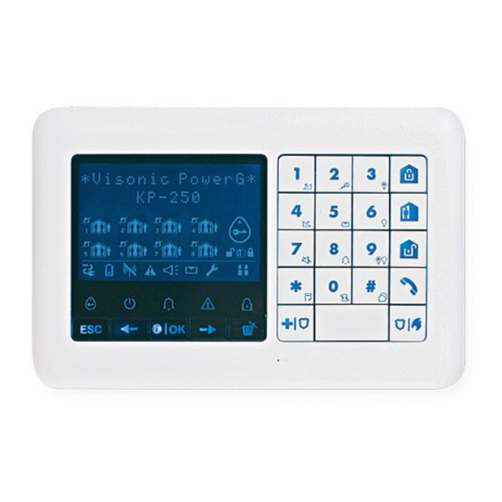
KP-250 PG2 is a 2-way wireless PowerG keypad display device for use with the PowerMaster-10 G2 / PowerMaster-30 G2 / PowerMaster-33 G2 control panel (version 18 and higher). Up to 10 KP-250 PG2 keypads can be enrolled in the PowerMaster system. The PowerMaster-10 G2, PowerMaster-30 G2, and PowerMaster-33 G2 are a highly advanced wireless alarm control panels produced by Visonic Ltd. -
Page 8: Wall Mounting
2.3 Wall Mounting The KP-250 PG2 is mounted as illustrated in the following drawing. 1. Drill 4 mounting holes 3. Line the two slots of the unit with the two hinges of the bracket, and then slide the unit downward on the bracket. -
Page 9: Enrollment Of The First Kp-250 Pg2 Keypad In Powermaster-33 G2
means scroll and select Note: If the KP-250 PG2 is already enrolled, you can configure the KP-250 PG2 parameters via the “Modify Devices” option – see Step 2. 2.5 Enrollment of the First KP-250 PG2 Keypad in PowerMaster-33 G2 The PowerMaster-33 G2 is designed to operate wirelessly with the KP-250 PG2 keypad installed anywhere within the protected premises. -
Page 10: Configuring The Kp-250 Pg2 Parameters
2.6 Configuring the KP-250 PG2 Parameters Enter the “Kxx.DEV SETTINGS” main menu on the KP-250 PG2 keypad immediately after enrollment or through the “MODIFY DEVICES” menu if performed at a later stage. Choose the number of the keypad device to configure and follow the configuration instructions for the KP-250 P-G2 keypad. - Page 11 2) When "SCREEN SAVER" in the 03:CONTROL PANEL menu is configured as "refresh by code", pressing any button on the KP-250 PG2 device and then entering the user code or presenting the proximity tag to the tag reader will return the device to normal display (see section 3.5.6, “Configuring Audible &...
-
Page 12: Programming
3. Programming 3.1 General Guidance This chapter explains the Installer programming (configuration) options of your KP-250 PG2 device and how to customize its operation to your particular needs end user requirements. The alarm system includes a partition feature. Partitioning allows you to have up to three independently controllable areas with different user codes assigned to each partition. -
Page 13: Entering The "Installer Mode" And Selecting A Menu Option
3.2 Entering the "Installer Mode" and Selecting a Menu Option All installer menu options can be accessed via the "Installer Mode" on the KP-250 PG2 keypad which is one of the main system menu options. The display on the keypad is on two rows. -
Page 14: Entering The "Installer Mode" If "User Permit" Is Enabled
• Installer: The "Installer" is authorized to access most but not all Installer Menu and sub-menu options. The default code is 8888 (*). • Guard Code: Enables an authorized guard to only Arm Away / Disarm the control panel. The default code is 0000 (*). D-306919 KP-250 PG2 Installer’s Guide... - Page 15 • Defining specific communication parameters – see "3:C.S REPORTING” in sections 3.6.1 and 3.6.4. • Resetting the KP-250 PG2 parameters to the default parameters – see "09:FACTORY DEFLT" in section 3.11. Note: Not every system includes a Master Installer code feature. In such systems, the Installer can access all Installer Menu and sub-menu options the same as a Master Installer.
-
Page 16: Identical Installer And Master Installer Codes
Use to enable the Soak Test for device zones. 3.4.6 Use to customize the defaults of the device's parameters according to DEFINE DEFAULTS 3.4.7 your personal preferences for each new device enrolled in the system. D-306919 KP-250 PG2 Installer’s Guide... -
Page 17: Adding New Wireless Devices Or Wired Sensors
Both Wireless and wired detectors can be enrolled in any zone number. To change the zone number, click the button or type in the zone number, and then press to confirm. Continue to Part B to configure the device – see diagram below D-306919 KP-250 PG2 Installer’s Guide... - Page 18 Press the enroll button for 2-5 seconds until the LED lights steadily and then release the button. The LED will extinguish or may blink for a few more seconds until the enrollment is completed. If enrollment is successfully completed, the KP-250 PG2 sounds the "Success Tune"...
- Page 19 Note: The Chime default appears on the second row of the keypad display. Partitions setting: Note: The "PARTITIONS" menu appears only if Partitions is enabled in the KP-250 PG2 (see section 3.13). When entering the menu, the display shows the default Partition selection (marked with Use the keypad keys to assign partitions to the device.
- Page 20 Zxx: ZONE TYPE This zone type generates an alarm when the system is armed both in AWAY 6 .Perimeter and HOME modes. Used for all sensors protecting the perimeter of the premises. D-306919 KP-250 PG2 Installer’s Guide...
- Page 21 This is a 24 hour zone operating all of the time even when the system is Zxx: ZONE TYPE disarmed. The tamper zone reports tamper alarm events from an external wired 20. Tamper device. The behavior is the same as opening the tamper switch of a detector. D-306919 KP-250 PG2 Installer’s Guide...
-
Page 22: Deleting A Device
Scroll the Device Group, identify (by zone and/or ID number) the exact device you wish to replace, for example: "Z01: Motion Sensor > ID No. 120-1254" and press the button. The display prompts you "<DEL> to Delete". To delete the device, press the (OFF) button. D-306919 KP-250 PG2 Installer’s Guide... -
Page 23: Modifying Or Reviewing A Device
From here on the process is same as the configuration process that follows the enrollment of that device. To continue, refer to Section 3.4.2 Part B. When done, the display will show the next device of the same type (i.e. "Motion camera"). D-306919 KP-250 PG2 Installer’s Guide... -
Page 24: Replacing A Device
If you try enrolling a new device of a different type than the replaced device, the alarm system will reject the new device and the display will read "WRONG DEV.TYPE". When done, the display shows the device details of the new device. D-306919 KP-250 PG2 Installer’s Guide... -
Page 25: Configuring Soak Test Mode
All Soak test zones will be reset to start a new test upon occurrence of one of the following: 1) Power up of the system; Setup of Factory Default; Change in system Soak Time. D-306919 KP-250 PG2 Installer’s Guide... -
Page 26: Defining Configuration Defaults For "Device Settings
3.4.7 Defining Configuration Defaults for "Device Settings" KP-250 PG2 enables you to define the Default Parameters used during enrollment and to change them whenever you wish so that new devices enrolled into the system will be configured automatically with these default parameters without the need to modify the configuration of each new enrolled device. -
Page 27: Updating Devices After Exiting Installer Mode
"Device Settings" configuration. During the updating period, the KP-250 PG2 display indicates "DEV UPDATING 018" where the number (for example, 018) is a countdown of the remaining number of devices yet to be updated. - Page 28 Contains a variety of other configurable features and parameters related to the 3.5.8 system. To enter the "03.CONTROL PANEL" menu and to select and configure an option, complete the following steps: Step 1 Select "03.Control Panel" INSTALLER MODE 03:CONTROL PANEL D-306919 KP-250 PG2 Installer’s Guide...
- Page 29 05:QUICK ARM 22:CROSS ZONING 32:DURESS ALARM 44:SIREN TIME 06:BYPASS ARM 33:INACTIVE ALRT 45:STROBE TIME Continues 07:LATCHKEY ARM 34:TAMPER ALARM 46:SIREN ON LINE Continues 09:ARMING KEY 35:AC FAIL RPRT 39:ALARM RESET Continues 40:ABORT FIRE T. Continues D-306919 KP-250 PG2 Installer’s Guide...
-
Page 30: Configuring Arming/Disarming And Exit/Entry Procedures
30 seconds Following entry, the user must disarm the KP-250 PG2 before the entry delay expires. 02:ENTRY DELAY2 Slow-rate warning beeps start sounding once the door is opened, until the last 10 seconds 15 seconds of the delay, during which the beeping rate increases. - Page 31 Define whether or not the user will be allowed to perform quick arming or not. Once quick 05:QUICK ARM arming is permitted, the KP-250 PG2 does not request a user code before it arms the system. Options: off and on (default in USA).
-
Page 32: Configuring Zones Functionality
(including tamper & power failure events of detectors, etc.). If the after 1 alarm number of alarms from a specific zone exceeds the programmed number, the KP-250 PG2 automatically bypasses the zone to prevent recurrent siren noise and excessive reporting to the Monitoring Station. -
Page 33: Configuring Alarms & Troubles
AC Fail message only if the AC power does not resume within a pre- after 5 minutes determined time delay. Options: after 5 minute, after 30 minute, after 60 minute or after 3 hours. D-306919 KP-250 PG2 Installer’s Guide... - Page 34 Note: In some PowerMaster variants, this menu is displayed in the Operation Mode only. 37:ABORT TIME The KP-250 PG2 can be configured to provide a delay before reporting an alarm to the in 30 seconds monitoring station (not applicable to alarms from 24H SILENT and EMERGENCY zones).
-
Page 35: Configuring Sirens Functionality
20 minutes Options: 5/10/20/40/60 minutes. Determine if the siren will be activated when the phone line fails and the system is 46:SIREN ON LINE armed. disable on fail Options: disable on fail or enable on fail. D-306919 KP-250 PG2 Installer’s Guide... -
Page 36: Configuring Audible & Visual User Interface
Options: on and off. You can activate or deactivate the "Low Battery Acknowledge" requirement from 54:LOW-BAT ACK the user whose keyfob's battery is low. Options: off – acknowledge not needed; on – acknowledge required. D-306919 KP-250 PG2 Installer’s Guide... - Page 37 Note: 1. To comply with EN requirements, "refresh by code" must be selected. 2. For Fire and Emergency keys, the first key press will produce the status display and will also perform the Fire/Emergency function. D-306919 KP-250 PG2 Installer’s Guide...
-
Page 38: Configuring Jamming And Supervision (Missing Device)
Note: To comply with EN requirements "EN standard" must be selected. 65:SMOK FAST MIS Determine that If the smoke detector does not report at least once within a time disable window of 200 seconds, a “MISSING” alert is initiated. Options: disable and enable D-306919 KP-250 PG2 Installer’s Guide... -
Page 39: Configuring Miscellaneous Features
Cellular GSM, GPRS, EMAIL, MMS or SMS and IP via broadband internet connection. The "04.COMMUNICATION" menu contains several sub-menu options, each covering a group of configurable features and parameters related to the communication and reporting as follows (see detailed list in Step 3 of the chart below): D-306919 KP-250 PG2 Installer’s Guide... - Page 40 Select "COMMUNICATION" INSTALLER MODE Step 2 Step 3 Step 4 Select the "Communication" Parameter you wish to configure Select Communication Sub-menu 1:PSTN TEL LINE 3.6.2 AREA CODE SKIP LINE PREFIX D-306919 KP-250 PG2 Installer’s Guide...
- Page 41 11:RCVR1 ACCOUNT 53:COM.FAIL RPRT 12:RCVR2 ACCOUNT 62:RECENT CLOSE 16:PSTN/GSM RCV1 63:ZONE RESTORE 17:PSTN/GSM RCV2 64:SYST.INACTIVE 21:IP RCVR1 65:TWO WAY VOICE 22:IP RCVR2 66:24H ZONE RPRT 26:SMS RCVR1 D-306919 KP-250 PG2 Installer’s Guide...
- Page 42 PG2 User’s Guide Private tel#4 SMS tel#4 REDIAL ATTEMPTS SMS PERMISSION VOICE->PRIVATE TEL.ACKNOWLEDGE 5:MOTION CAMERA IMAGE FORWARD 3.6.6 VIEW ON DEMAND VIEW TIME WINDOW e-mail#1 VIEW OTHER ALARM e-mail#2 e-mail#3 e-mail#4 MMS tel#1 MMS tel#2 D-306919 KP-250 PG2 Installer’s Guide...
-
Page 43: Configuring Pstn (Landline Phone) Connection
Formats (see section 3.6.4 option 41) and to Private Telephones (see section 3.6.5 "VOICE REPORT"). Here you configure necessary parameters related to the PSTN telephone line to which the PowerMaster is connected. ⋅⋅⋅ ⋅⋅⋅ 04:COMMUNICATION 1:PSTN TEL LINE MENU you wish D-306919 KP-250 PG2 Installer’s Guide... -
Page 44: Configuring Gsm-Gprs (Ip) - Sms Cellular Connection
Options: disable; enable. GSM REPORT Define whether the system will report events to the Monitoring Stations' Alarm Format receivers disable via the GSM Voice (analog) Channel. For further information, see section 3.6.4 option 41. Options: disable; enable. D-306919 KP-250 PG2 Installer’s Guide... - Page 45 (Mobile Network Code) numbers. GPRS ALWAYS ON Define whether the control panel will stay continuously connected "enable", via GPRS disable communication, or disconnect "disable", after each report session. Previously known as "SESSION TIMEOUT" Options: Enable or Disable. D-306919 KP-250 PG2 Installer’s Guide...
-
Page 46: Configuring Events Reporting To Monitoring Stations
RPRT CHAN"; option and define which of the communication channels the system disabled will use as the main reporting channel. To define also backup reporting channels, enter the "2nd RPRT CHAN" and "3rd RPRT CHAN" options and define them as well. 04:3rd RPRT CHAN disabled D-306919 KP-250 PG2 Installer’s Guide... - Page 47 The dialer waits 5 seconds for a dial tone and goes on hook if none is received. Applicable only at the 1 digit. [#] [4] The dialer waits 5 seconds. Applicable only in the middle of the number. D-306919 KP-250 PG2 Installer’s Guide...
- Page 48 Report Events option (option 01) to two IP Receivers, 000.000.000.000 Visonic PowerManage model. IP reporting can be performed via GPRS (IP) channel using SIA IP format or via Broadband IP channel using SIA IP or Visonic PowerNet format.
- Page 49 Options "BROADBAND FAIL" after 1/2/5/15/30 min, 1/3/6 hours and do not report (default). 61:RPRT CNF ALRM Define whether the system will report whenever 2 or more events (confirmed alarm) occur rprt disabled during a specific period or enable the report and bypass the detector. D-306919 KP-250 PG2 Installer’s Guide...
- Page 50 High (default setting). If it is a very quiet environment, set to Low. (Return) Master Installer only for: Send 2wv code / voice <− −>cs / Refers to PowerMaster-30 G2 with voice option. D-306919 KP-250 PG2 Installer’s Guide...
- Page 51 Define whether 24 hour (silent and audible) zones will function as normal 24 hour zones or as 66:24h ZONE RPRT both burglary panic zones. Applicable in UK only Options: audible as panic; silent as panic; both as panic; and both burglary. D-306919 KP-250 PG2 Installer’s Guide...
- Page 52 all(-alrm) Alarms All but alarms Disable report None None Note: “all” means that all 5 Groups are reported including Trouble messages - sensor / system low battery, sensor inactivity, power failure, jamming, communication failure etc. D-306919 KP-250 PG2 Installer’s Guide...
-
Page 53: Configuring Events Reporting To Private Users
"On Demand" and to forward them as defined in the PowerManage application. To protect customers' privacy, the KP-250 PG2 can be customized to enable the "On Demand View" only during specific system modes (i.e. Disarm, Home and Away) and also to a specific time window following an alarm event. In this section you can program the 4 e-mail addresses and mobile phone numbers to which the images will be forwarded and to configure the parameters of the "On Demand View". -
Page 54: Configuring Upload / Download Remote Programming Access Permission
Perim-Follow / Inter-Follow / Exit/Entry 1 / Exit/Entry 2. 3.6.7 Configuring Upload / Download Remote Programming Access Permission Using a PC, the KP-250 PG2 can be configured (by upload/download) either locally or from remote via PSTN telephone line or GPRS cellular communication. - Page 55 Enable or disable the remote access to the system. If disabled, the system cannot be Remote access accessed remotely thereby inhibiting the Upload/Download and the Remote Control via enable PSTN or GSM analog communication channels (refer to the KP-250 PG2 User's Guide, Chapter 7). Options: enable; disable. Mast. UL/DL code...
- Page 56 PowerMaster will call back the PowerManage server using "IP RCVR 1" / "IP RCVR 2" 2nd caller ID# address as configured in Section 5.6.4, options 21 and 22. Note: Caller ID#1/ID#2 must contain at least 6 digits otherwise the process will not work. (Return) D-306919 KP-250 PG2 Installer’s Guide...
-
Page 57: Broadband
Resets all broadband settings Press ‘ OK ‘ Define the availability of the PowerLink communicator during AC failure. PLINK ON AC FAIL Options: shutdown (PowerLink is turned off during AC failure; default), active 10 min D-306919 KP-250 PG2 Installer’s Guide... - Page 58 Configuration Instructions (PowerLink is turned off if AC failure duration is longer than 10 minutes), or active (PowerLink will always be active). Note: Keeping the PowerLink communicator active during AC failure reduces battery backup time significantly. D-306919 KP-250 PG2 Installer’s Guide...
-
Page 59: Pgm Output
Configure the EXP-33 expanders I/O types to either Zone or PGM. Pin #1 to #6 by default are configured to Zone, pin #7 to #8 are configured to PGM. Select the pin # and depending on the physical setup select either Zone or PGM. D-306919 KP-250 PG2 Installer’s Guide... - Page 60 Step 4 Step 5 Select either "Zone" or "PGM" to Press to return to “Set EXP I/O configure the I/O type PINS ” or to take you to “<OK> to Exit" OPTIONS OPTIONS D-306919 KP-250 PG2 Installer’s Guide...
-
Page 61: Pgm Connection
05:OUTPUTS PGM Outputs PGM-on Expander Step 4 Step 6 Step 5 KP-250 PG2 displays currently PIN# Select "silent" or "audible" options Press to return to “PGM Outputs” or to take you to “<OK> to Exit" PGM OPTIONS... - Page 62 Select "none" or "Expander IOV ID Select "NO EXISTING DEV." or " Pmm: no. 441-XXXX" options PGM PIN #m" options PGM on HWExpndrs NO EXISTING DEV. NO EXISTING DEV. Pmm: PGM PIN #m E0x:Expander IOV ID NO. 441-XXXX D-306919 KP-250 PG2 Installer’s Guide...
-
Page 63: Custom Names
Note: To enter the Location name use the "String Editor" below. IMPORTANT! The editing of a custom zone name automatically deletes the original text and recorded voice name. Make sure to record a new voice name via the RECORD ZONE NAME menu (see next section). D-306919 KP-250 PG2 Installer’s Guide... - Page 64 Clears digits of the string 'm', 'M', 'n', 'N', 'o', 'O', '6' 'p', 'P', 'q', 'Q', 'r', 'R', 's', 'S', '7' 't', 'T', 'u', 'U', 'v', 'V', '8' 'w', 'W', 'x', 'X', 'y', 'Y', 'z', 'Z', '9' D-306919 KP-250 PG2 Installer’s Guide...
-
Page 65: Record Speech
) 0%. A progress indicator will be displayed that is incremented each time by 25%, as follows: 0%, 25%, 50%, 75%, 100%. At the end of the recording process, the KP-250 PG2 will display the following: "RECORDING ENDED". Release the button. -
Page 66: Voice Box Mode
The "07.DIAGNOSTICS" menu contains several sub-menu options, each covering a group of configurable features and parameters related to the communication and reporting as follows (see the list in Step 3 of the chart below): Refers to system that is connected to the Voice Box D-306919 KP-250 PG2 Installer’s Guide... - Page 67 Select sub-menu option Select the diagnostics you want to perform TEST ALL DEVICES TEST ALL DEVICES WL DEVICES SHOW ALL DEVICES SHOW RF PROBLEMS TEST ONE DEVICE MOTION SENSORS SHOCK SENSORS D-306919 KP-250 PG2 Installer’s Guide...
-
Page 68: Testing Wireless Devices
Enter the "WL DEVICES" menu, select the type of test you wish to perform (see guidance above and in section 3.9.1), and then refer to the table below which provides you with detailed explanations for each option. Option Instructions You can test all devices automatically, one after the other. TEST ALL DEVICES D-306919 KP-250 PG2 Installer’s Guide... - Page 69 The devices are tested in the following order: wall-mounted devices, vanishing magnetic contact devices, keyfobs and panic buttons. At the end of the test process, the KP-250 PG2 will present the following: "SHOW ALL DEVICES". Press to view devices' status.
-
Page 70: Testing The Gsm Module
Option Instructions At the end of the test process, the KP-250 PG2 will present the devices' status: "Zxx: 24hr: <status>" "Zxx: NOW: <status>" Note: Refer to "SHOW ALL DEVICES" section for further information on device status. SHOW ALL DEVICES You can view the devices status. -
Page 71: Testing The Sim Number
. The panel sends a test SMS to the server. If the server receives the SMS, the KP-250 PG2 will display “SIM# verified” and the test ends successfully. If the SMS was not received, for example, if there is no connection between the control panel and server, the KP-250 PG2 will display “SIM not verified”. -
Page 72: Testing The Broadband/Powerlink Module
Receiver 1 or 2 is inaccessible, as follows: • Wrong receiver IP has been entered. RCVR#1 UNREACH • Receiver failure. BROADBAND MODULE • WAN Network failure. RCVR#2 UNREACH BROADBAND MODULE The PowerMaster unit is not registered to IP receiver 1 or 2. D-306919 KP-250 PG2 Installer’s Guide... -
Page 73: User Settings
3.11 Factory Default The FACTORY DEFLT menu enables you to reset the KP-250 PG2 parameters to the factory default parameters or to delete all the PowerG devices that are enrolled in the system. To obtain the relevant parameters defaults, contact the PowerMaster dealer. - Page 74 Exit". Notes: 1. For KP-250 PG2 with 2 installer codes, INSTALLER code and MASTER INSTALLER code, only the master installer code enables to perform the factory default function. 2. If the Soak Test is active, performing factory default will restart the Soak Test.
-
Page 75: Serial Number
The SERIAL NUMBER menu enables reading the system serial number and similar data for both PowerMaster control panel and KP-250 PG2 keypad for support purposes only. To read the system serial number and other relevant data, complete the following steps:... -
Page 76: Partitioning
ID NO. 441- YYYY vx.x.xx LOCAL KP-250 to Step 1 3.13 Partitioning 3.13.1 General Guidance – "Partitioning" Menu This menu allows you to enable/disable partitions in the system (for further details, see APPENDIX B). D-306919 KP-250 PG2 Installer’s Guide... -
Page 77: Enabling / Disabling Partitions
Note: If "normal / EN-50131 / INCERT" is selected, the control panel will operate according to the OTHERS setup configuration (see section 3.14.6). The following options normal, Incert, and CP01 are not available for all configurations. D-306919 KP-250 PG2 Installer’s Guide... -
Page 78: Bs8243 Setup
BS8243 – KF-234 PG2 and KF-235 PG2. all - All devices can trigger a panic alarm Applies only when the keyfob is defined as "skip exit delay" (for further details, see the keyfob's User's Guide) D-306919 KP-250 PG2 Installer’s Guide... - Page 79 5 minutes that "cancel alarm" time, a “cancel alarm” message is sent to the Monitoring Station indicating that the alarm was canceled by the user. Options: in 1/5/15/60 minute/s; in 4 hours and not active D-306919 KP-250 PG2 Installer’s Guide...
-
Page 80: Dd243 Setup
06:CONFIRM PANIC A confirmed panic alarm is reported if one of the following occurs within the Applies only when the keyfob is defined as "skip exit delay" (for further details, see the keyfob's User's Guide) D-306919 KP-250 PG2 Installer’s Guide... - Page 81 5 minutes within that "cancel alarm" time, a “cancel alarm” message is sent to the Monitoring Station indicating that the alarm was canceled by the user. Options: in 1/5/15/60 minute/s; in 4 hours and not active D-306919 KP-250 PG2 Installer’s Guide...
-
Page 82: Cp01 Setup
09:ENTRY DELAY 2 seconds of the delay, during which the beeping rate increases. Locations No. 1 (entry Applies only when the keyfob is defined as "skip exit delay" (for further details, see the keyfob's User's Guide) D-306919 KP-250 PG2 Installer’s Guide... -
Page 83: Others Setup Or En50131 Setup
PowerMaster panel keypad ("on entry all."). The "Exit Delay" time can be further adjusted according to your preferred exit route. 03:END EXIT MODE The KP-250 PG2 provides you with the following "Exit Mode" options: normal D-306919 KP-250 PG2 Installer’s Guide... - Page 84 Define the “cancel alarm” period that starts upon reporting an alarm to the Monitoring in 5 minutes Station. If the user disarms the system within that time period, a “cancel alarm” message is sent to the Monitoring Station. Options: not active and in 1/5/15/60 minutes; in 4 hours D-306919 KP-250 PG2 Installer’s Guide...
-
Page 85: Periodic Test By Installer Code
To conduct a periodic test, make sure the system is disarmed and then enter the "PERIODIC TEST" menu using your installer code (8888 by default) or master installer code (9999 by default). Immediately after entering the "PERIODIC TEST" menu, all 4 LEDs on the panel and all 5 LEDs on the KP-250 PG2 keypad will momentarily light (LED test). - Page 86 The KP-250 PG2 reads the temperature and light intensity of the zone. When testing, all previous temperature and light results from sensors are cleared. To display the temperature and light intensity of zones on the KP-250 PG2, press . After 20 seconds, the KP-250 PG2 displays the temperature, the sensor number and the sensor location, as in the following example: "Z01 24.5°C"...
- Page 87 The KP-250 PG2 reads the device number, followed by the device type (for example, Contact Sensor, Motion Sensor or Keyfob) and followed by the device location. At...
- Page 88 At this stage, activate each input of the shock detector in turn. Depending on shock detector model, one of the following may appear instead: "Zxx:Shk+AX" / " Zxx:Shk+CntG3" /" Zxx:Shk+CntG2". D-306919 KP-250 PG2 Installer’s Guide...
- Page 89 Press ; the following screen will appear: "Zxx ACTIVATE NOW". Activate the input of the detector; the following screens will appear: "<Zxx IS ACTIVATE>" "<OK> SEND IMAGE". D-306919 KP-250 PG2 Installer’s Guide...
-
Page 90: Handling System Troubles
AC power supply connector. GAS TROUBLE CO Gas detector: Replace the detector. Move the Panel and GSM unit to The GSM communicator is not able to another location. connect to the cellular network. GSM NET FAIL D-306919 KP-250 PG2 Installer’s Guide... - Page 91 There is no power to the siren Make sure that the AC power supply is connected properly SIREN AC FAILURE The sensor has an open tamper Close sensor tamper TAMPER OPEN The sensor reports trouble Replace the sensor TROUBLE D-306919 KP-250 PG2 Installer’s Guide...
-
Page 92: Reading The Event Log
Event Log is erased Returns to normal operating mode KP-250 00:00 READY <OK> to Exit - Reading Events While the system is in the normal operating mode, press the key. D-306919 KP-250 PG2 Installer’s Guide... - Page 93 Press to revert to normal operating mode. Clicking the button repeatedly at any stage in the procedure takes you one level up with each click. Clicking the button will take you to “<OK> TO EXIT”. D-306919 KP-250 PG2 Installer’s Guide...
-
Page 94: Appendix A: Specifications
Average relative humidity of approx. 75% non-condensing. For 30 days per year, relative humidity may vary from 85% to 95% non-condensing. Dimensions (WxLxD) 150x100x20mm (5-7/8 x 3-7/8 x 13/16 in) Weight (including battery and bracket) 379 g (13 oz). Mounting Wall-mounted or desktop Color White D-306919 KP-250 PG2 Installer’s Guide... -
Page 95: Appendix B: Working With Partitions
When partition mode is enabled, all zones, user codes, and features of the control panel are automatically assigned to Partition 1. B1. User Interface and Operation Refer to the KP-250 PG2 User's Guide, APPENDIX B. PARTITIONING for a detailed description of the user interface (Arming/Disarming, siren behavior, show function, etc.). B2. Common Areas When partitions cross over, the area common to the partitions must be assigned a zone. - Page 96 Note: A Soak Test of Common areas cannot be initiated when one of its partitions is armed. When Soak Test of a Common area is active, an alarm event is ignored unless all the partitions that are assigned to the zone are armed. D-306919 KP-250 PG2 Installer’s Guide...
-
Page 97: Appendix C: Glossary
Bypassed zones will not be protected throughout the arming period. Even if restored to normal (closed), bypassed zones will remain unprotected until the system is disarmed. Permission to “force arm” is given or denied by the installer while programming the system. D-306919 KP-250 PG2 Installer’s Guide... - Page 98 State: AWAY, HOME, AWAY-INSTANT, HOME-INSTANT, LATCHKEY, FORCED, BYPASS. Status: AC fail, low battery, trouble, etc. User Codes: The KP-250 PG2 is designed to obey your commands, provided that they are preceded by a valid security access code. Unauthorized people do not know this code, so any attempt on their part to disarm or defeat the system is bound to fail.
- Page 99 (24-hour) zones are “on watch” regardless of whether the system is armed or not. Zone Type: The zone type determines how the system handles alarms and other signals sent from the device. D-306919 KP-250 PG2 Installer’s Guide...
-
Page 100: Appendix D: Compliance With Standards
– Connect the device to an outlet on a circuit different from the one which supplies power to the receiver. – Consult the dealer or an experienced radio/TV technician. Changes or modifications not expressly approved by Visonic Ltd. could void the user's authority to operate the equipment. W.E.E.E. Product Recycling Declaration For information regarding the recycling of this product you must contact the company from which you orignially purchased it. - Page 101 WARRANTY THE MANUFACTURER SHALL IN NO EVENT BE LIABLE FOR Visonic Limited (the “Manufacturer") warrants this product only (the ANY SPECIAL, INDIRECT, INCIDENTAL, CONSEQUENTIAL OR "Product") to the original purchaser only (the “Purchaser”) against PUNITIVE DAMAGES OR FOR LOSS, DAMAGE, OR EXPENSE,...
- Page 102 Arming and Disarming the System Icon/Key Indications Arming Indication ARM AWAY ARM HOME DISARM EXIT DELAY The icons appear consecutively Programming Functionality String Editor Functionality ‘.’, ‘0’ ‘.’, ‘,’, ‘1’ ‘a’, ‘A’, ‘b’, ‘B’, ‘c’, ‘C’, ‘2’ ‘d’, ‘D’, ‘e’, ‘E’, ‘f’, ‘F’, ‘3’ ‘g’, ‘G’, ‘h’, ‘H’, ‘i’, ‘I’, ‘4’...
-
Page 103: Volume Up
1. Volume up 13. ARM AWAY 25. The system is in INSTALLER MODE or USER SETTINGS 2. Record a message 14. ARM HOME 26. Sabbath mode 3. PGM on 15. DISARM 27. Instructs the user to present the proximity tag (at the position of this indication) 4. - Page 104 Guide Keypad Installer’s Guide Keypad Installer’s Guide Keypad Installe eypad Installer’s Guide Keypad Installer’s Guide Keypad Installer’s Guid staller’s Guide Keypad Installer’s Guide Keypad Installer’s Guide Keypa Contact Visonic for further information: Guide Keypad Installer’s Guide Keypad Installer’s Guide Keypad Installe info@visonic.com...
Need help?
Do you have a question about the KP-250 PG2 and is the answer not in the manual?
Questions and answers