
Related Manuals for Supermicro Supero SC933 Series


Summary of Contents for Supermicro Supero SC933 Series
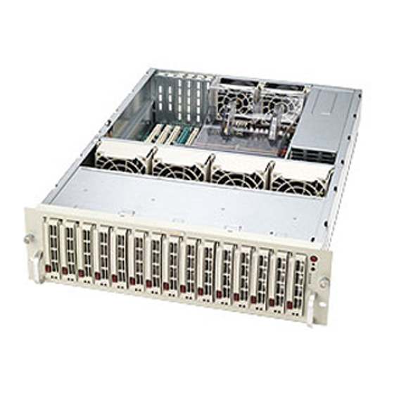
- Page 1 UPER ® SC933 Chassis Series SC933S1-R760B SC933S2-R760B SC933T-R760B SC933E1-R760B SC933E2-R760B USER’S MANUAL 2.0b...
- Page 2 This product, including software and documentation, is the property of Supermicro and/or its licensors, and is supplied only under a license. Any use or reproduction of this product is not allowed, except as expressly permitted by the terms of said license.
- Page 3 SC933 chassis. Installation and maintenance should be performed by experienced technicians only. Supermicro's SC933 chassis provides high-capacity storage in a 3U form factor. The design features fifteen hot-swappable 3.5" hard drive bays, with triple redundant power supplies and dual redundant cooling fans, while optimizing rack mounting space.
-
Page 4: Manual Organization
This section lists compatible cables, power supply specifications, and compatible backplanes. Not all compatible backplanes are listed. Refer to our Web site for the latest compatible backplane information. NOTE: Customers requiring support for SCSI backplanes may contact Supermicro's Technical Support department directly. -
Page 5: Table Of Contents
Chapter 1 Introduction Overview ......................1-1 Shipping List ....................1-1 Part Numbers ....................1-1 Where to get Replacement Components ............1-2 Contacting Supermicro ..................1-3 Returning Merchandise for Service..............1-4 Chapter 2 System Safety Overview ......................2-1 Warnings and Precautions ................2-1 Preparing for Setup .................. - Page 6 SC933 Chassis Manual Chapter 5 Rack Installation Overview ......................5-1 Unpacking the System ..................5-1 Preparing for Setup ..................5-1 Choosing a Setup Location ................5-1 Rack Precautions .................... 5-2 General Server Precautions ................5-2 Rack Mounting Considerations ............... 5-3 Ambient Operating Temperature ..............
-
Page 7: Chapter 1 Introduction
Chapter 1 Introduction Overview Supermicro’s SC933 chassis features a unique and highly-optimized design. The chassis is equipped with high-efficiency power supplies while high-performance fans provide ample optimized cooling for the system. Fifteen hot-swappable drive bays offer maximum storage capacity in a 3U form factor. -
Page 8: Where To Get Replacement Components
Supermicro Authorized Distributors/ System Integrators/Resellers. A list of Supermicro Authorized Distributors/System Integrators/Reseller can be found at: http://www.supermicro.com. Click the Where to Buy link. NOTE: Customers requiring support for SCSI backplanes may contact Supermicro's Technical Support department directly. -
Page 9: Contacting Supermicro
Super Micro Computer, Inc. 980 Rock Ave. San Jose, CA 95131 U.S.A. Tel: +1 (408) 503-8000 Fax: +1 (408) 503-8008 Email: marketing@supermicro.com (General Information) support@supermicro.com (Technical Support) Web Site: www.supermicro.com Europe Address: Super Micro Computer B.V. Het Sterrenbeeld 28, 5215 ML... -
Page 10: Returning Merchandise For Service
For faster service, RMA authorizations may be requested online (http://www. supermicro.com/support/rma/). Whenever possible, repack the chassis in the original Supermicro carton, using the original packaging material. If these are no longer available, be sure to pack the chassis securely, using packaging material to surround the chassis so that it does not shift within the carton and become damaged during shipping. -
Page 11: Chapter 2 System Safety
Chapter 2: System Safety Chapter 2 System Safety Overview This chapter provides a quick setup checklist to get your chassis up and running. Following the steps in order given should enable you to have your chassis set up and operational within a minimal amount of time. This quick setup assumes that you are an experienced technician, famailiar with common concepts and terminology. -
Page 12: Electrical Safety Precautions
SC933 Chassis Manual Electrical Safety Precautions Basic electrical safety precautions should be followed to protect yourself from harm and the SC933 from damage: • Be aware of the locations of the power on/off switch on the chassis as well as the room’s emergency power-off switch, disconnection switch or electrical outlet. -
Page 13: General Safety Precautions
Chapter 2: System Safety • DVD-ROM laser: CAUTION - this server may have come equipped with a DVD-ROM drive. To prevent direct exposure to the laser beam and hazardous radiation exposure, do not open the enclosure or use the unit in any uncon- ventional way. - Page 14 SC933 Chassis Manual • Touch a grounded metal object before removing any board from its antistatic bag. • Do not let components or PCBs come into contact with your clothing, which may retain a charge even if you are wearing a wrist strap. •...
-
Page 15: Chapter 3 System Interface
Chapter 3: System Interface Chapter 3 System Interface Overview There are several LEDs on the control panel as well as others on the drive carriers to keep you constantly informed of the overall status of the system as well as the activity and health of specific components. -
Page 16: Control Panel Buttons
SC933 Chassis Manual Control Panel Buttons There are three push-buttons located on the front of the chassis. These are, in order from top to bottom, a power on/off button, reset button and a mute button. Power: The main power switch is used to apply or remove power from the power supply to the server system. - Page 17 Chapter 3: System Interface Power: Indicates power is being supplied to the system's power supply units. This LED should normally be illuminated when the system is operating. Overheat/Fan Fail: When this LED flashes it indicates a fan failure. When continu- ously on (not flashing) it indicates an overheat condition, which may be caused by cables obstructing the airflow in the system or the ambient room temperature being too warm.
-
Page 18: Drive Carrier Leds
SC933 Chassis Manual Drive Carrier LEDs Your chassis uses SAS or SCSI drives, but not both. SAS Drives Each SAS drive carrier has two LEDs. • Green: Each SAS drive carrier has a green LED. When illuminated, this green LED (on the front of the SAS drive carrier) indicates drive activity. A connection to the SAS backplane enables this LED to blink on and off when that particular drive is being accessed. -
Page 19: Chapter 4 Chassis Setup And Maintenance
Chapter 4: Chassis Setup and Maintenance Chapter 4 Chassis Setup and Maintenance Overview This chapter covers the steps required to install components and perform mainte- nance on the chassis. The only tool you will need to install components and perform maintenance is a Phillips screwdriver. -
Page 20: Removing The Chassis Cover
SC933 Chassis Manual Removing the Chassis Cover Release Tab Figure 4-1: Removing the Chassis Cover Removing the Chassis Cover 1. Press both tabs simultaneously. 2. Slide the cover back toward the rear of the chassis. 3. Lift the cover off the chassis. Warning: Except for short periods of time, do NOT operate the server without the cover in place. -
Page 21: Installing Hard Drives
Chapter 4: Chassis Setup and Maintenance Installing Hard Drives Figure 4-2: Removing Hard Drive Carriers Hard drives are mounted in drive carriers to simplify their installation and removal from the chassis. These carriers also help promote proper airflow within the drive bays. - Page 22 5. Secure the hard drive to the tray using four screws. 6. Replace the drive tray into the chassis. Make sure to close the drive tray handle to lock the drive tray into place. Warning: Only enterprise level hard drives are recommended for use in Supermicro chassis.
-
Page 23: Installing The Motherboard
Chapter 4: Chassis Setup and Maintenance Installing the Motherboard The I/O shield holds the motherboard ports in place. Install the I/O shield before installing the motherboard. I/O shield Installing the I/O Shield 1. Review the documentation that came with your motherboard. Become familiar with component placement, requirements, and precautions. -
Page 24: Expansion Slot Setup
SC933 Chassis Manual 5. Secure the CPU(s), heatsinks, and other components to the motherboard as described in the motherboard documentation. 6. Connect the cables between the motherboard, backplane, chassis, front panel, and power supply. The fans may be temporarily removed to allow ac- cess to the backplane ports. -
Page 25: Installing The Air Shroud
Chapter 4: Chassis Setup and Maintenance Installing the Air Shroud Rear Fans Air Shroud Air Shroud Extension Figure 4-4: Air Shroud for SC933 Chassis Air shrouds concentrate airflow to maximize fan efficiency. The SC933 chassis air shroud does not require tools to set it up. Installing the Air Shroud 1. - Page 26 SC933 Chassis Manual Checking the Server's Air Flow 1. Make sure there are no objects to obstruct airflow in and out of the server. In addition, if you are using a front bezel, make sure the bezel's filter is replaced periodically.
-
Page 27: Installing System Fans
Chapter 4: Chassis Setup and Maintenance Installing System Fans Six heavy duty fans provide cooling for the chassis. These fans circulate air through the chassis as a means of lowering the chassis internal temperature. Release Tab Figure 4-5: System Fan Replacing a System Fan 1. - Page 28 SC933 Chassis Manual Figure 4-6: Replacing the System Fans 4-10...
-
Page 29: Replacing The Power Supply
The SC933 chassis includes three redundant power suppies that can be changed without powering down the system. In the unlikely event of a power failure, a new unit can be ordered directly from Supermicro (see the contact information in the Preface). - Page 30 SC933 Chassis Manual Release Tab Figure 4-7: Removing the Power Supply Changing the Power Supply 1. This chassis includes triple redundant power supplies which allow the server to remain running while one or two power supplies are removed. 2. Push the release tab (on the back of the power supply), as illustrated. 3.
-
Page 31: Changing The Power Distributor
Chapter 4: Chassis Setup and Maintenance Figure 4-8: Changing the Power Distributor Changing the Power Distributor Server chassis that are 2U and higher require a power distributor. The power dis- tributor provides failover and power supply redundancy. In the unlikely event you must change the power distributor, do following. - Page 32 SC933 Chassis Manual Notes 4-14...
-
Page 33: Chapter 5 Rack Installation
Chapter 5: Rack Installation Chapter 5 Rack Installation Overview This chapter provides instructions for installing your chassis into a rack. Following these steps in the order given should enable you to have the chassis installed within a minimum amount of time. Unpacking the System You should inspect the box the chassis was shipped in and note if it was damaged in any way. -
Page 34: Rack Precautions
SC933 Chassis Manual • This product is for installation only in a Restricted Access Location (dedicated equipment rooms, service closets and similar environments). Warnings and Precautions! Rack Precautions • Ensure that the leveling jacks on the bottom of the rack are fully extended to the floor with the full weight of the rack resting on them. -
Page 35: Rack Mounting Considerations
Chapter 5: Rack Installation • Always keep the rack's front door and all panels and components on the servers closed when not servicing to maintain proper cooling. Rack Mounting Considerations Ambient Operating Temperature If installed in a closed or multi-unit rack assembly, the ambient operating tempera- ture of the rack environment may be greater than the ambient temperature of the room. -
Page 36: Rack Mounting Instructions
SC933 Chassis Manual Rack Mounting Instructions This section provides information on installing the SC933 chassis into a rack unit with the rails provided. There are a variety of rack units on the market, which may mean the assembly procedure will differ slightly. You should also refer to the instal- lation instructions that came with the rack unit you are using. - Page 37 Chapter 5: Rack Installation Figure 5-2: Installing the Inner Rails Installing the Inner Rail Extensions 1. Place the inner rail extensions on the side of the chassis aligning the hooks of the chassis with the rail extension holes. Make sure the extension faces "outward"...
- Page 38 SC933 Chassis Manual Front Side Figure 5-3: Assembling the Outer Rails Installing the Outer Rails to the Rack 1. Attach the shorter outer rail bracket to the outside of the longer outer rail bracket. You must align the pins with the slides. Also, both bracket ends must face the same direction.
- Page 39 Chapter 5: Rack Installation Figure 5-4: Installing the Outer Rails to the Server Rack...
- Page 40 SC933 Chassis Manual Figure 5-5: Installing the Chassis Installing the Chassis into a Rack 1. Confirm that chassis inner rails and outer rails are installed on the rack. 2. Line chassis rails with the front of the rack rails.. 3. Slide the chassis rails into the rack rails, keeping the pressure even on both sides (you may have to depress the locking tabs when inserting).
-
Page 41: Appendix A Cables, Screws, And Other Accessories
This appendix lists supported cables for your chassis system. It only includes the most commonly used components and configurations. For more compatible cables, refer to the manufacturer of the motherboard you are using and our Web site at: www.supermicro.com. A-2 Cables Included with SC933T Chassis (SAS) SC933T-R760... -
Page 42: Alternate Sas Cables
SC933 Chassis Manual A-4 Cables Included with SC933E Series Chassis SC933E1-R760 and SC933E2-R760 Part # Type Length Description CBL-0180L-02 39 cm iPass to iPass SAS cable CBL-0209L Cable 210 mm 4-pin to 3-pin fan power cable Cable Two regional power cords A-5 Compatible Cables These cables are compatible with the SC933 Chassis. -
Page 43: Extending Power Cables
Appendix A: Chassis Cables Extending Power Cables Although Super Micro chassis are designed with to be efficient and cost-effective, some compatible motherboards have power connectors located in different areas. To use these motherboards you may have to extend the power cables to the mother boards. - Page 44 SC933 Chassis Manual A-6 Chassis Screws The accessory box includes all the screws needed to setup your chassis. This section lists and describes the most common screws used. Your chassis may not require all the parts listed. HARD DRIVE Flat head Pan head 6-32 x 5 mm 6-32 x 5 mm...
-
Page 45: Appendix B Sc933 Power Supply Specifications
Appendix B: Power Supply Specifications Appendix B SC933 Power Supply Specifications This appendix lists power supply specifications for your chassis system. 760W Power Supply MFR Part # PWS-0065 100 - 240V AC Voltage 50 - 60Hz 14 - 8 Amp DC Ouput 5V + 3.3V ≤ 200W +5V 36.0 Amp +5V standby 3.5 Amp +12V 50.0 Amp (combined) - Page 46 SC933 Chassis Manual Notes...
-
Page 47: Appendix C Sas-933El Backplane Specifications
Appendix C SAS-933EL Backplane Specifications Appendix C SAS-933EL Backplane Specifications To avoid personal injury and property damage, carefully follow all the safety steps listed below when accessing your system or handling the components. C-1 ESD Safety Guidelines Electrostatic Discharge (ESD) can damage electronic com ponents. To prevent dam- age to your system, it is important to handle it very carefully. - Page 48 This manual reflects SAS-933EL Revision 1.12 the most current release available at the time of publication. Always refer to the Supermicro Web site at www.supermicro. com for the latest updates, compatible parts and supported configurations.
-
Page 49: Front Connectors
Appendix C SAS-933EL Backplane Specifications C-5 Front Connectors and Jumpers BUZZER_ENB1 FANFAIL1 5V_LED 12V_LED REMOTE_FAN_FAIL_SCOKET BUZZER1 SAS933EL R658 REV 1.12 PRI_IPMI PRI_I2C OVERHEATFAIL1 R659 PRI_BLINK SEC_J2 SEC_IPMI SEC_I2C SEC_J0 SEC_J1 PRI_J2 PRI_J0 PRI_J1 SEC_BLINK PRI_EXP PRI_MODE4 BAR CODE PRI_MODE5 SEC_MODE4 SEC_FLASH PRI_FLASH SEC_MODE5... - Page 50 SC933 Chassis Manual C-6 Front Connector and Pin Definitions 1. Primary and Secondary I C Connectors C Connector Pin Definitions The I C connectors are used to monitor the Pin# Definition power supply and to control the fans. See Data the table on the right for pin definitions. There Ground are two connectors, one primary and one Clock...
- Page 51 Appendix C SAS-933EL Backplane Specifications 6. Fan Connectors Fan Connectors (Fan1, Fan2, Fan3, The 3-pin connectors, designated Fan1, Fan2, and Fan4) Fan3, and Fan4, provide power to the system Pin# Definition fans. See the table on the right for pin defini- Ground tions.
- Page 52 SC933 Chassis Manual C-7 Front Jumper Locations and Pin Definitions SAS933EL REV 1.12 PRI_BLINK SEC_J2 SEC_J0 SEC_J1 PRI_J2 SEC_J0 PRI_J0 SEC_J1 PRI_J2 SEC_BLINK PRI_EXP PRI_BLINK SEC_BLINK BUZZER_ENB1 FANFAIL1 5V_LED 12V_LED REMOTE_FAN_FAIL_SCOKET SAS933EL BUZZER1 R658 REV 1.12 R659 PRI_IPMI PRI_I2C OVERHEATFAIL1 PRI_BLINK SEC_I2C SEC_J2 SEC_IPMI SEC_J0 SEC_J1 PRI_J2 PRI_J0...
-
Page 53: Explanation Of Jumpers
Appendix C SAS-933EL Backplane Specifications General Jumper Settings Jumper Jumper Settings Note Factory setting PRI_MODE4 Do not change Factory setting PRI_MODE5 Do not change Factory setting PRI_BLINK Open Do not change Factory setting SEC_MODE4 Do not change Factory setting SEC_MODE5 Do not change Factory setting SEC_BLINK... -
Page 54: Front Led Indicators
SC933 Chassis Manual Front LED Indicators BUZZER_ENB1 FANFAIL1 5V_LED 12V_LED REMOTE_FAN_FAIL_SCOKET SAS933EL BUZZER1 R658 REV 1.12 R659 PRI_IPMI PRI_I2C OVERHEATFAIL1 PRI_BLINK SEC_I2C SEC_J2 SEC_IPMI SEC_J0 SEC_J1 PRI_J1 PRI_J2 PRI_J0 SEC_BLINK PRI_EXP PRI_MODE4 BAR CODE PRI_MODE5 SEC_MODE4 SEC_FLASH PRI_FLASH SEC_MODE5 FAN1 +12V +12V +12V... - Page 55 Appendix C SAS-933EL Backplane Specifications C-8 Rear Connectors and LED Indicators SAS #0 FAIL#1 ACT#1 SAS #1 FAIL#2 ACT#2 SAS #2 FAIL#3 ACT#3 SAS #3 FAIL#4 ACT#4 SAS #4 FAIL#5 ACT#5 SAS #5 FAIL#6 ACT#6 SAS #6 FAIL#7 ACT#7 SAS #7 FAIL#8 ACT#8 SAS #8...
- Page 56 SC933 Chassis Manual Rear LED Indicators Rear LED Hard Drive Activity Failure LED SAS #0 ACT #1 FAIL #1 SAS #1 ACT #2 FAIL #2 SAS #2 ACT #3 FAIL #3 SAS #3 ACT #4 FAIL #4 SAS #4 ACT #5 FAIL #5 SAS #5 ACT #6...
-
Page 57: Single Ports
Appendix C SAS-933EL Backplane Specifications Single and Dual Port Expanders Single Ports SAS-933EL1 backplanes have a single port expander that access all fifteen drives and supports cascading. BUZZER_ENB1 FANFAIL1 5V_LED 12V_LED REMOTE_FAN_FAIL_SCOKET SAS933EL R658 BUZZER1 REV 1.12 PRI_IPMI PRI_I2C OVERHEATFAIL1 R659 PRI_BLINK SEC_J2... -
Page 58: Single Host Bus Adapter
SC933 Chassis Manual C-10 Failover The SAS-933EL2 backplane has two expanders which allow effective failover and recovery. Single Host Bus Adapter SAS HBA In a single host bus configuration, the backplane connects to one Host Bus Adapter (HBA). SEC_J2 SEC_J0 SEC_J1 PRI_J2 PRI_J1... - Page 59 Appendix C SAS-933EL Backplane Specifications C-11 Failover with RAID Cards and Multiple HBAs The SAS-933EL backplane may be configured for failover with multiple HBAs using either RAID controllers or HBAs to acheive failover protection. RAID Controllers: If RAID controllers are used, then the failover is accomplished through port failover on the same RAID card.
- Page 60 SC933 Chassis Manual C-12 Cables and Chassis Power Card Chassis Power Card In a cascaded configuration, the first chassis includes a motherboard and, at least one, HBA. Other servers in this enclosed system, include a power card. This section describes the supported power card for the SAS-933 backlplane system. J BPW R2 REV 1.
- Page 61 Appendix C SAS-933EL Backplane Specifications Connecting an Internal Host Bus Adapter to the Backplane The following section lists the most common cables used to connect the HBA to the backplane. SEC_J2 SEC_J0 SEC_J1 PRI_J2 PRI_J1 PRI_J2 PRI_J0 PRI_J1 Single Internal Host Bus Adapter SEC_J2 SEC_J0 SEC_J1...
- Page 62 SC933 Chassis Manual Supported Internal HBA to Backplane Cables Use the following listed cables to create connections between the internal HBA and backplane. The cables required depend on the HBA connector. Figure C-11: iPass to 4-lane Cable (CBL-0117) Cable Name: iPass to 4-Lane Part #: CBL-0117 Length: 46 cm (18 inches) Description: This cable has one SFF-8484 (32-pin) connector on one end and iPass...
- Page 63 Appendix C SAS-933EL Backplane Specifications Figure C-12: iPass (Mini-SAS) to iPass (Mini-SAS) (CBL-0110L-2) Cable Name: iPass (Mini-SAS) to iPass (Mini-SAS) Part #: CBL-0108L-02 Length: 39 cm (15 inches) Part #: CBL-0109L-02 Length: 22 cm (9 inches) Part #: CBL-0110L-02 Length: 18 cm (7 inches) Description: This cable has an iPass (SFF-8087/Mini-SAS) connector (36-pin) at each end.
- Page 64 SC933 Chassis Manual Connecting an External Host Bus Adapter to the Backplane This backplane supports external Host Bus Adapters. In this configuration, the HBA and the backplane are in different physical chassis. This allows a JBOD (Just a Bunch Of Drives) configuration from an existing system. SEC_J2 SEC_J0 SEC_J1...
- Page 65 Appendix C SAS-933EL Backplane Specifications Supported External HBA to Backplane Cable Use the following cable if your external HBA has an InfiniBand connector. Figure C-14: SAS InfiniBand to Mini-SAS (CBL-0200L) Cable Name: SAS InfiniBand to Mini-SAS X4 1M cable, PBF Part #: CBL-0200L Length: 1 meter Description: This cable has an InfiniBand connector (SFF-8470) on one end and an SFF-8088-1X (26-pins) at the other end.
- Page 66 SC933 Chassis Manual Connecting Multiple Backplanes in a Single Channel Environment This section describes the cables used when cascading from a single HBA. These connections use CBL-0167L internal cables and CBL-0166L external cables. Single HBA Conguration CBL-0167L SEC_J2 SEC_J0 SEC_J1 PRI_J2 PRI_J1 with Single Port Assembly...
- Page 67 Appendix C SAS-933EL Backplane Specifications Single HBA Configuration Cables Single Port Cable Assembly FigureC-16: SAS Internal Backplane Cable (CBL-0167L) Cable Name: SAS EL2/EL1 Backplane Cable (Internal) w/ 2-port Cascading Cable, 68 cm Part #: CBL-0167L (SFF-8087 to SFF-8088 x1) Ports: Single Placement: Internal cable Description: Internal cable.
- Page 68 SC933 Chassis Manual Connecting Multiple Backplanes in a Dual Channel Environment This section describes the cables used when cascading from a single HBA. These connections use CBL-0168L internal cables and CBL-0166L external cables. SEC_J2 SEC_J0 SEC_J1 PRI_J2 PRI_J1 Cable 0168L Port B Expander 2 Port A Expander 1 with Single Port Assembly...
- Page 69 Appendix C SAS-933EL Backplane Specifications Dual HBA Conguration Cables Dual Port Cable Assembly Figure C-19: SAS Cascading Cable Internal (CBL-0168L) Cable Name: SAS Dual Port Cable Assembly, 68/76 cm Part #: CBL-0168L Placement: Internal cable Ports: Dual Description: Internal cascading cable. This cable connects the backplane to the HBA or external port.
- Page 70 SC933 Chassis Manual C-13 Supported Cascading Configurations Cascading allows the system to access data at a faster rate by allowing several backplanes to share resources to reduce latency time. The first backplane in a cascaded system requires a motherboard and HBA. Other servers require a power control card, but not a motherboard and HBA together.
- Page 71 Appendix C SAS-933EL Backplane Specifications Server System with Single SAS HBA The exanders allow horizontal branching. This configuration also applies to dual ports. SEC_J2 SEC_J2 SEC_J0 SEC_J0 SEC_J1 PRI_J2 PRI_J1 SEC_J1 PRI_J2 PRI_J1 Port A Expander 1 Port A Expander 1 Power Card PRI_J2 PRI_J0...
- Page 72 SC933 Chassis Manual Server System with Dual SAS HBA and Cascading Configuration SEC_J2 SEC_J0 SEC_J1 PRI_J2 PRI_J1 Port A Expander 1 Port B Expander 2 PRI_J1 PRI_J2 PRI_J0 Dual Port Cable Assembly Cable 0168L (internal cable) Cable 0166L SEC_J2 SEC_J0 SEC_J1 PRI_J2 PRI_J1...
- Page 73 Appendix C SAS-933EL Backplane Specifications Server System with Dual SAS HBA SEC_J2 SEC_J0 SEC_J1 PRI_J2 PRI_J1 Port B Ex. 2 Port A Ex. 1 SEC_J2 SEC_J0 SEC_J1 PRI_J2 PRI_J1 Port B Ex. 2 Port A Ex. 1 PRI_J2 PRI_J0 PRI_J1 Power Card PRI_J2...
- Page 74 SC933 Chassis Manual Dual Cable Routing External Cables In the previous diagrams external cables are represented with two differ- CBL-0166L ent line patterns. These cables are both (external cable) CBL-0166L external cables. Different lines help you determine the cable routing. C-28...
-
Page 75: Appendix D Sata-933 Backplane Specifications
Appendix D: SATA-933 Backplane Specifications Appendix D SATA-933 Backplane Specifications To avoid personal injury and property damage, carefully follow all the safety steps listed below when accessing your system or handling the components. D-1 ESD Safety Guidelines Electrostatic Discharge (ESD) can damage electronic com ponents. To prevent dam- age to your system, it is important to handle it very carefully. - Page 76 This manual reflects SATA-933 Revision 3.00 the most current release available at the time of publication. Always refer to the Supermicro Web site at www. supermicro. com for the latest updates, compatible parts and supported confgurations.
- Page 77 Appendix D: SATA-933 Backplane Specifications Front Connectors and Jumpers UPER SATA933 REV 3.00 Figure D-1: Front Connectors and Jumpers Front Connectors 1. OH#1: JP25 2. OH#2: JP45 3. Power Connectors (4-pin): JP10, JP13, JP46 and JP48 4. Fan Connectors: JP54, JP56, JP58 and JP60 5.
- Page 78 SC933 Chassis Manual UPER SATA933 REV 3.00 Figure D-2: SATA Ports 11. SATA Port #5: J12 12. SATA Port #6: J14 13. SATA Port #7: J16 14. SATA Port #8: J22 15. SATA Port #9: J23 16. SATA Port #10: J24 17.
- Page 79 Appendix D: SATA-933 Backplane Specifications D-5 Front Connector and Pin Definitions 1. - 2. OH Temperature Connector OH#1: JP25 and OH#2: JP45 Open: 45 degrees Celcius 1-2: 50 degrees Celcius 2-3: 55 degrees Celcius 3. Backplane Main Power Connectors Backplane Main Power The 4-pin connectors designated JP10, 4-Pin Connector (JP10, JP13, JP13, JP46 and JP48 provide power to the...
-
Page 80: Fan Jumper Settings
SC933 Chassis Manual D-6 Front Jumper Locations and Pin Definitions JP18 UPER SATA933 REV 3.00 JP61 JP62 JP63 JP64 Figure D-3: Front Jumpers Socket Settings Socket Socket Setting Note Buzzer Reset JP18 Connected to front panel Press once to disable buzzer; Press twice to enable buzzer Fan Jumper Settings This backplane supports up to four fans. - Page 81 Appendix D: SATA-933 Backplane Specifications Front LED Indicators FAN FAIL #1 ALARM +12V #2 #3 LEDs LEDs UPER SATA933 SATA933 REV 3.00 UPER SATA933 REV 3.00 Figure D-4: Front Jumpers Front Panel LEDs Normal State Specification Fan #1 Fail Failure in Fan #1 Fan #2 Fail Failure in Fan #2 Fan #3 Fail...
- Page 82 SC933 Chassis Manual D-7 Rear Connectors and LED Indicators SATA#2 SATA#4 SATA#0 SATA#6 SATA#10 SATA#8 SATA#14 SATA#12 SATA#7 SATA#9 SATA#11 SATA#5 SATA#1 SATA#3 SATA#13 Figure D-5: Rear Connectors Rear SATA Connectors Rear SATA Drive Connector Number SATA #0 SATA HDD #0 SATA #1 SATA HDD #1 SATA #2...
- Page 83 Appendix D: SATA-933 Backplane Specifications FAIL #2 FAIL #4 FAIL #0 FAIL #6 FAIL #10 FAIL #8 FAIL #14 FAIL #12 D14/D7 D18/D19 D12/D5 D22/D23 D27/D32 D25/D30 D42/D39 D40/D37 FAIL #7 FAIL #9 SATA#11 FAIL #5 FAIL #1 FAIL #3 SATA#13 D24/D29 D26/D31...
- Page 84 SC933 Chassis Manual Disclaimer (cont.) The products sold by Supermicro are not intended for and will not be used in life sup- port systems, medical equipment, nuclear facilities or systems, aircraft, aircraft devices, aircraft/emergency communication devices or other critical systems whose failure to per- form be reasonably expected to result in significant injury or loss of life or catastrophic property damage.
Need help?
Do you have a question about the Supero SC933 Series and is the answer not in the manual?
Questions and answers