Sign In
Upload
Download
Table of Contents
Contents
Add to my manuals
Delete from my manuals
Share
URL of this page:
HTML Link:
Bookmark this page
Add
Manual will be automatically added to "My Manuals"
Print this page
×
Bookmark added
×
Added to my manuals
Manuals
Brands
Supermicro Manuals
Chassis
Supero SC933S1-R760B
User manual
Supermicro SC933S1-R760B User Manual
Sc933 chassis series
Hide thumbs
Also See for SC933S1-R760B
:
User manual
(84 pages)
1
2
3
4
5
6
7
8
9
10
11
12
13
14
15
16
17
18
19
20
21
22
23
24
25
26
27
28
29
30
31
32
33
34
35
36
37
38
39
40
41
42
43
44
45
46
47
48
49
50
51
52
53
54
55
56
57
58
59
60
61
62
63
64
65
66
67
68
69
70
71
72
73
74
75
76
77
78
79
80
81
82
83
84
page
of
84
Go
/
84
Contents
Table of Contents
Bookmarks
Table of Contents
Table of Contents
Chapter 1 Introduction
Preface
Manual Organization
Table of Contents
Overview
Shipping List
Part Numbers
Where to Get Replacement Components
Contacting Supermicro
Chapter 2 System Safety
Electrical Safety Precautions
Overview
Preparing for Setup
Warnings and Precautions
General Safety Precautions
System Safety
Chapter 3 System Interface
Overview
Control Panel Buttons
Control Panel Leds
Drive Carrier Leds
SAS Drives
SCSI Drives
Chapter 4 Chassis Setup and Maintenance
Overview
Installation Steps
Installation Step 1: Remove the Chassis Cover
To Remove the Chassis Cover
Installation Step 3: Installing the Motherboard
I/O Shield
Permanent and Optional Standoffs
To Install the I/O Shield
Add-On Card/Expansion Slot Setup
To Install Add-On and Expansion Cards
To Install the Motherboard
Installation Step 5: Installing the Air Shroud
To Install the Air Shroud
Installation Complete
To Check the Server's Air Flow
System Fans
Replacing a System Fan
Power Supply
To Change the Power Supply
To Change the Power Distributor
Chapter 5 Rack Installation
Overview
Preparing for Setup
Choosing a Setup Location
Ambient Operating Temperature
General Server Precautions
Rack Mounting Considerations
Rack Precautions
Circuit Overloading
Mechanical Loading
Reduced Airflow
Reliable Ground
Unpacking the System
Rack Mounting Instructions
Identifying the Sections of the Rack Rails
Inner Rail Extension
To Install the Inner Rails
To Install the Outer Rails to the Rack
To Install the Chassis into a Rack
Appendices
A-1 Overview
Appendix A Cables, Screws, and Other Accessories
Cables Included with SC933S Chassis (SCSI
A-2 Cables Included with SC933T Chassis (SAS)
A-3 Cables Included with SC933S Chassis (SCSI)
Cables Included with SC933T Chassis (SAS
A-4 Cables Included with SC933E Series Chassis
A-5 Compatible Cables
Alternate SAS Cables
Extending Power Cables
Front Panel to the Motherboard
A-6 Chassis Screws
Sas 933El Series Backplane
Table of Contents
Contacting Supermicro
An Important Note to Users
Chapter 1: Safety Guidelines
ESD Safety Guidelines
General Safety Guidelines
2-1 Front Connectors and Jumpers
Front Connectors
Chapter 2: Jumper Settings and Pin Definitions
Front Connector and Pin Definitions
Front Jumper Locations and Pin Definitions
Explanation of Jumpers
Front Led Indicators
Rear Connectors and Led Indicators
Single and Dual Port Expanders
Failover
Single Host Bus Adapter
Single Host Bus Adapter Failover
Dual Host Bus Adapter
Cables and Chassis Power Card
Supported Cascading Configurations
Advertisement
Quick Links
Download this manual
S
UPER
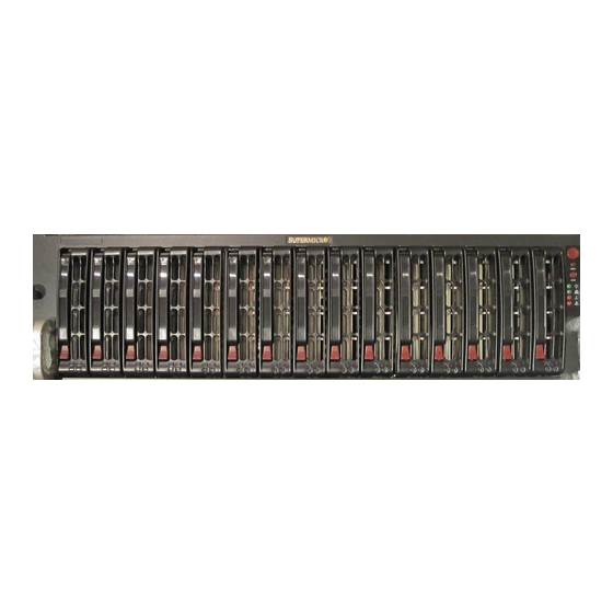
SC933 CHASSIS SERIES
!
SC933S1-R760B
SC933T-R760B
SC933E1-R760B
SC933E2-R760B
USER'S MANUAL
2.0
Table of
Contents
Previous
Page
Next
Page
1
2
3
4
5
Advertisement
Chapters
Table of Contents
7
Table of Contents
55
Table of Contents
Need help?
Do you have a question about the SC933S1-R760B and is the answer not in the manual?
Ask a question
Questions and answers
Related Manuals for Supermicro SC933S1-R760B
Chassis Supermicro Supero SC933 Series User Manual
Sc933 chassis series (84 pages)
Chassis Supermicro SC942i-550 Installation Manual
Sc942 chassis series (32 pages)
Chassis Supermicro Supero SC936 Series User Manual
Sc936 series (84 pages)
Chassis Supermicro Supero SC933T-R760B User Manual
Sc933 chassis series (84 pages)
Chassis Supermicro SC946LE1C-R1K66JBOD User Manual
(92 pages)
Chassis Supermicro SCF418 Series User Manual
Supero scf418 series (87 pages)
Chassis Supermicro SC826BE1C-R920LPB User Manual
Sc826 series chassis (134 pages)
Chassis Supermicro SC815 series User Manual
(54 pages)
Chassis Supermicro SCE102 User Manual
(40 pages)
Chassis Supermicro SC813MF2 Series User Manual
(58 pages)
Chassis Supermicro SC825TQC-R802LPB User Manual
(98 pages)
Chassis Supermicro SC216 Series User Manual
(169 pages)
Chassis Supermicro SCE300 User Manual
(39 pages)
Chassis Supermicro SC721TQ-350B2 User Manual
(42 pages)
Chassis Supermicro SC815B User Manual
(55 pages)
Chassis Supermicro SUPERO SC813MTQ-350CB User Manual
(84 pages)
This manual is also suitable for:
Sc933e1-r760b
Sc933e2-r760b
Sc933t-r760b
Table of Contents
Print
Rename the bookmark
Delete bookmark?
Delete from my manuals?
Login
Sign In
OR
Sign in with Facebook
Sign in with Google
Upload manual
Upload from disk
Upload from URL


Need help?
Do you have a question about the SC933S1-R760B and is the answer not in the manual?
Questions and answers