Alliance Laundry Systems UCN020HN2 Programming Manual
Hide thumbs
Also See for UCN020HN2:
- Operation & maintenance manual (20 pages) ,
- Original instructions manual (75 pages)
Table of Contents

Subscribe to Our Youtube Channel
Related Manuals for Alliance Laundry Systems UCN020HN2


Summary of Contents for Alliance Laundry Systems UCN020HN2
- Page 1 Washer-Extractor Refer to Page 5 for Model Numbers CHM1311R CHM1311R Keep These Instructions for Future Reference. (If this machine changes ownership, this manual must accompany machine.) Part No. F8237801R8 www.alliancelaundry.com May 2013...
- Page 3 NOTE: The WARNINGS and IMPORTANT SAFETY INSTRUCTIONS appearing in this WARNING manual are not meant to cover all possible conditions and situations that may occur. Common sense, Machine installations must comply with caution, and care must be exercised when installing, minimum specifications and requirements maintaining, or operating the machine.
-
Page 4: Table Of Contents
Table of Model Identification ................Preliminary Information..............About the Control ................. Contents Glossary of Terms................. Power Failure Recovery ............... Communications ................... Control Identification................. Select Cycle Pads.................. Display Identification ................. Light Emitting Diodes (LEDs) ............. Wash LED..................Rinse LED..................Spin LED ..................Door LED.................. - Page 5 How to Enter Cycle Programming........... 24 How to Exit Programming Feature ..........24 How to Program Cycle Agitate “AgIt” ..........24 How to Exit Programming Feature ..........24 How to Program Cycle Segment “SEg1” ........25 How to Exit Programming Feature ..........25 How to Exit Programming Feature ..........
- Page 6 Testing Machine and Electronic Control Functions......38 How to Enter Diagnostic Testing Feature........38 How to Start Tests................38 How to Exit Diagnostic Testing Feature.......... 38 Diagnostic Test Descriptions..............39 VFD Balance Weight Test (Design 1 Models) ........ 39 Drive DC Bus Display Test (Design 2 Models) ......39 Water Purge Test................
-
Page 7: Model Identification
Model Identification Information in this manual is applicable to these machine models: HCL020HN2 HCU040HN2 SCU030HNF UCN040HNV HCL030HN2 HCU040HNF SCU040HN2 UCN060HN2 HCL030HNF HCU060HNF SCU040HNF UCN060HNF HCL040HN2 HCZ020HN2 SCU060HN2 UCN060HNV HCL040HNV SLC020HN2 SCU060HNF UCN080HNF HCL060HN2 SCL020HNF SCU080HNF UCN080HNV HCL060HNV SCL030HN2 SCZ020HN2 UCU020HN2 HCL080HNF SCL030HNF UCL020HN2... -
Page 8: Preliminary Information
Preliminary Information About the Control Power Failure Recovery This control is an advanced, programmable computer If a cycle is in progress and the power fails for less that lets the owner control most machine features by than five seconds, the cycle status is saved in memory. pressing a sequence of keypads. -
Page 9: Control Identification
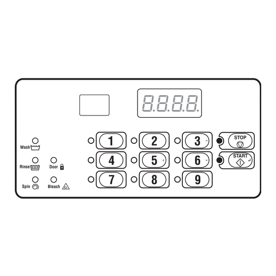
Control Identification Select Cycle Pads The Select Cycle pads are used in various combinations for programming cycles, retrieving audit (Refer to Figure 1) information, running diagnostic tests, and other operations. These instructions cover the manual Select Cycle pads are used to select the specific programming and data retrieval options. -
Page 10: Display Identification
Display Identification Light Emitting Diodes (LEDs) Door LED (Refer to Figure 1) Door LED is lit whenever the door is locked. The door can’t be opened when this LED is lit. Light Emitting Diodes (LEDs) are used to indicate the chosen cycle, cycle status, when the bleach Bleach LED compartment is dispensing, and door lock information. -
Page 11: Machine Operation
Machine Operation Start Up Run Mode When power is applied to the machine, the control will The control enters this mode when a cycle is running. display its software version as “S xx” (“xx” is the The time remaining appears in the display, the status version number) for one (1) second. -
Page 12: Special Features
Special Features Programming Control Rapid Advance Feature The control allows the machine owner to program the This feature allows the user to quickly advance control with the use of the keypad. Cycle options may through active cycles. This feature is useful when tests be programmed, audit information may be viewed and must be performed immediately on a machine diagnostic tests may be run by pressing combinations... -
Page 13: Opening The Top Cover
Opening the Top Cover To manually program the control, the top cover must 3. Lift the top cover up. To completely remove, lift be opened. Opening and closing the top cover trips a top cover away from both top cover hinges. Refer switch which allows access to various programming to Figure 2. -
Page 14: Entering The Manual Mode
Entering the Manual Mode Manual Programming For programming, testing, and retrieving information from the control, it is often necessary to enter the Manual Programming (Prog) Manual Mode by following the six simple steps below. Manual Read Audit (AUdt) For an overview of Entering the Manual Mode, refer to the flowchart on the following page. - Page 15 Entering the Manual Mode Manual Mode : Enter by opening To enter a programming top cover. Then press #4 and #1 option, press the START (enter) keypads pads at same time. keypad. To exit, press the #5 ( ) keypad. >...
-
Page 16: Programming Control
Programming Control What Can Be Programmed? Each description includes instructions on when and why the option might be used and, more importantly, This feature allows the owner to program cycle how to program the option. information and other features by using the keypads. For more advanced users, a quick reference list (refer The control must have the Manual Programming to Table 2) and programming flowcharts (refer to... - Page 17 Programming Control Table 2 (continued) Option Option Default Description Value Range Number Display Value “FILL” Fill Step – – a. “FLEn” Fill Step Enable/Disable on/oFF b. “FLEU” Fill Level HI/nEd/Lo “tEnP” Fill Temperature CoLd/Uarn/Hot “SUPL” Supply Step – – a. “SUEn” Supply Step Enable/Disable on/oFF “dISP”...
- Page 18 Programming Control Table 2 (continued) Option Option Default Description Value Range Number Display Value “SnIn” Extract Minutes Intermediate Extract: Min. Step Time = 30 seconds Max. Step Time = 3:59 minutes Final Extract: Min. Step Time = 30 seconds Max. Step Time = 9:59 minutes d.
- Page 19 Programming Control “Prog” - Manual Programming “dCYC” - Set the default cycle and temperature “Aud” - Program when the signal will sound “E FL” - Fill Error “E dr” - Drain Error “E Ub” - Unbalance Error (VFD only) “E oP” - Open Thermistor Error (Models with Heat) “Err”...
- Page 20 Programming Control (continued) (continued) (continued) “C2” or “S1” - “SUEn” - Supply Step Enable/Disable: “C2” - Compartment #2 Compartment #2/ “on” = Enabled “on” = Enable Supply #1: “oFF” = Disabled “oFF” = Disable “on” = Enabled (Design 2 Models) “oFF”...
- Page 21 Programming Control (continued) “SUPC” (Design 1 only) - Dispenser: Choose either supply dispenser “S” = Supply Dispenser or compartment dispenser. “C” = Compartment Dispenser “bALr” (VFD only) - Program the number of times control will retry balancing the load before moving to extract step: 1-7. “IrA”...
- Page 22 Programming Control “dIAg” Diagnostic Tests To enter a programming option, press the START (enter) Press the keypad. To exit, press the START (enter) keypad. #5 ( ) keypad. > Press the #3 ( ) or the “d019” “d019” - Drive DC Bus #6 ( ) keypad to scroll VFD Balance Weight Test Display Test...
-
Page 23: How To Program Default Cycle
Programming Control Default Cycle “dCYC” Audio Signal “AUd” This option allows the owner to set the default cycle This option allows the owner to program when the the machine will enter when in the Ready Mode. signal will sound. There are two occasions when a signal may sound How to Program Default Cycle during operation. -
Page 24: How To Read Table
Programming Control How to Read Table 3 Coin/ Start Remove Card To determine the correct number required to program Signal Mode Card End of Input the Audio Signal, use the following chart. The Signal Value (Not (Not Cycle Pressed (Not used) used) Value column contains the number required in step 6. -
Page 25: How To Program Error Code Programming
Programming Control Error Code Programming “Err-” “E FL” Fill Error This option allows the owner to turn on or turn off “E dr” Drain Error certain errors in the control. “E Ub” Unbalance Error Display (VFD only) How to Program Error Code Programming “E oP”... -
Page 26: How To Enter Cycle Programming
Programming Control Cycle Programming “CyC-” How to Program Cycle Agitate “AgIt” This option allows the owner to program the cycle’s This option allows the owner to program different agitation action and speed. These options apply to the aspects for various steps in each type of cycle. There entire cycle. -
Page 27: How To Program Cycle Segment "Seg1
Programming Control How to Program Cycle Segment “SEg1” Programming Fill Step There are eight (8) programmable cycle segments. 1. When “FILL” appears in the display, press the Within each segment, there are several programmable START (enter) keypad. The first Fill step options. -
Page 28: How To Exit Programming Feature
Programming Control Programming Supply Step 5. Press the START (enter) keypad when the desired status/value appears in the display. The 1. When “SUPL” appears in the display, press the next Supply step option will appear in the START (enter) keypad. The first Supply step display. -
Page 29: How To Exit Programming Feature
Programming Control Programming Agitate Step Programming Drain Step 1. When “AgSt” appears in the display, press the 1. When “drAn” appears in the display, press the START (enter) keypad. The first Agitate step START (enter) keypad. The current status will be programming option will appear in the display. -
Page 30: How To Exit Programming Feature
Programming Control Programming Extract Step Extract Description Status/Value Step 1. When “SPIn” appears in the display, press the START (enter) keypad. The first Extract step “SPEn” Extract Step “on”/“oFF” programming option will appear in the display. Enable/Disable 2. Press the #3 ( ) or the #6 ( ) keypad to scroll “SSEC”... -
Page 31: How To Program Cycle Time "Cnin
Programming Control Supply/Compartment Dispenser How to Program Cycle Time “Cnin” Programming “SUPC” (Design This option allows the owner to program minutes to 1 Models only) the cycle’s display time. 1. Press the #3 ( ) or the #6 ( ) keypad to scroll This option allows the owner to choose between the through the programmable Cycle Programming supply dispenser or compartment dispenser. -
Page 32: How To Program Number Of Balance Retries
Programming Control Number of Balance Retries IR Access (On/Off) “IrA” “bALr” (Variable Frequency This option allows the owner to enable or disable Drives Only) allowing the control to be read by an external device. How to Program the IR Access (On/Off) This option allows the owner to program how many times the control will retry balancing the load before 1. -
Page 33: How To Program Fahrenheit/Celsius
Programming Control Fahrenheit/Celsius “t FC” Hot Water Temperature “FH” This option allows the owner to set whether the This option allows the owner to program the hot water display will be shown in Fahrenheit or Celsius. temperature for models equipped with heat. How to Program Fahrenheit/Celsius How to Program Hot Water Temperature 1. -
Page 34: How To Program Warm Water Temperature
Programming Control 10. Warm Water Temperature 11. Cold Water Temperature “FC” “FHC” This option allows the owner to program the cold water temperature for models equipped with heat. This option allows the owner to program the warm water temperature for models equipped with heat. How to Program Cold Water Temperature How to Program Warm Water Temperature 1. -
Page 35: How To Program Cool Down Enable/Temperature
Programming Control 12. Cool Down Enable/Temperature 13. Production Test Cycle (On/Off) “Codn” “PtEn” This option allows the owner to enable or disable the This option allows the owner to enable or disable Cool Down Water Temperature option. If enabled, the access to the production test cycle. -
Page 36: How To Program The Manual Rapid Advance (On/Off)
Programming Control 14. Manual Rapid Advance (On/Off) 15. No Cycle Time Display “nCtd” “rAEn” This option allows the owner to enable or disable whether the cycle time will appear in the display. This option allows the owner to enable or disable the rapid advance feature. -
Page 37: How To Program Programmable Cycle Time Display
Programming Control 16. Programmable Cycle Time 17. Slow Drain Detection Adjust Display “PCtd” Value “SdAd” This option allows the owner to program the displayed This option allows the owner to increase the slow cycle time. drain detection threshold by adding additional seconds to the threshold value. -
Page 38: Collecting Audit Information
Collecting Audit Information How to Read Audit Data This feature allows the owner to retrieve audit information stored in the machine by pressing a 1. Use the #3 ( ) or the #6 ( ) keypad to scroll sequence of pads on the control. through various options until the desired option is How to Enter Audit Feature shown in the display. -
Page 39: Manual Reset
Manual Reset This feature allows the owner to reset the machine control’s programming data to the factory default settings by pressing a sequence of pads on the control. How to Enter Manual Reset 1. Control must be in Manual Mode to start. Refer to Entering the Manual Mode. -
Page 40: How To Enter Diagnostic Testing Feature
Testing Machine and Electronic Control Functions How to Enter Diagnostic Testing Feature This feature allows the owner to run diagnostic tests on various machine operations without servicing the 1. Control must be in Manual Mode. Refer to machine. The following tests are available: Entering the Manual Mode. -
Page 41: Testing Machine And Electronic Control Functions
Testing Machine and Electronic Control Functions Diagnostic Test Descriptions Water Purge Test This option empties all water from the machine. VFD Balance Weight Test (Design 1 Models) To start test, control must be in the Diagnostic Testing Mode. Refer to How to Enter Diagnostic Testing This test is only available on machines equipped with Feature at the beginning of this section. -
Page 42: Drive Software Version Number Test (Design
Testing Machine and Electronic Control Functions Production Test Cycle Drive Software Version Number Test (Design 2 models only) To Enter Production Test Cycle This option displays the custom drive software version 1. Be certain control is in Ready Mode and top number. - Page 43 Testing Machine and Electronic Control Functions Production Test Cycle Quick Reference Chart Display Test Cycle Step Comments “S xx” FEC Control Software Version xx is the software version number. “o xx” Output Board Software Version xx is the software version number. “Ct 2”...
- Page 44 Testing Machine and Electronic Control Functions Table 13 (continued) Production Test Cycle Quick Reference Chart Display Test Mode Comments “xxxF” degrees F or Heat water to 110°F or display temperature xxx is degree temperature. This step “xxxC” degrees C skipped if not model with heat. Heater depending on the turned off when temperature reached.
-
Page 45: Error Codes
Error Codes Following is a list of possible error codes for an external device Infra-red communication errors. All electronic control. Errors beginning with “EI” refer to other errors refer to machine errors. Cause/ Display Description Corrective Action EI01 Transmission Failure Communication failure. - Page 46 Error Codes Table 14 (continued) Cause/ Display Description Corrective Action E do Door Open Error Control detects door open. Caused by pulling on door while locked or about to lock. Correct inoperative door locking system. End cycle. Power down machine to clear.
- Page 47 Error Codes Table 14 (continued) Cause/ Display Description Corrective Action Water Leak Detection Error Control senses an increase in water level during E LF** diagnostic testing. Power down machine to clear. Control shows error after door is open (when cycle is completed) for one minute or after test has been completed, the right-most decimal point on display lights* and the error information will be logged in audit...
-
Page 48: Rapid Advance Feature
Rapid Advance Feature How to Exit Rapid Advance Feature The Rapid Advance feature allows the owner to quickly advance through active cycles. 1. Advance through the cycles until reaching the How to Use Rapid Advance Start Mode. Control must be in an active cycle to use the Rapid NOTE: The Rapid Advance option must be turned Advance feature. -
Page 49: Communications Mode
Communications Mode Infra-red Communications The Infra-red Communications feature allows the control to communicate with an external device. The control can be programmed without using the keypad. How to Begin Communications with An External Device The control will go blank and the display will show “-C-”... -
Page 50: Cycle Charts
Cycle Charts Domestic Model Cycle Chart Perm Cotton/ Perm Cotton/ Perm Cotton/ Rags Press Terry Press Terry Press Terry Delicates Heavy Reclaim Cycle Steps Light Light Medium Medium Heavy Heavy Cold Soil Soil Soil Soil Soil Soil Soil Cycle reference CYC1 CYC2 CYC3... - Page 51 Cycle Charts (continued) Domestic Model Cycle Chart Perm Cotton/ Perm Cotton/ Perm Cotton/ Rags Press Terry Press Terry Press Terry Delicates Heavy Reclaim Cycle Steps Light Light Medium Medium Heavy Heavy Cold Soil Soil Soil Soil Soil Soil Soil Cycle reference CYC1 CYC2 CYC3...
- Page 52 Cycle Charts (continued) International Model Cycle Chart Cycle Steps Cycle reference CYC1 CYC2 CYC3 CYC4 CYC5 CYC6 CYC7 CYC8 CYC9 (display in Program Mode) 18/3/18 18/3/18 18/3/18 18/3/18 18/3/18 18/3/18 18/3/18 3/12/3 3/12/3 Agitation type Normal Normal Normal Normal Normal Normal Normal Gentle...
- Page 53 Cycle Charts (continued) International Model Cycle Chart Cycle Steps Cycle reference CYC1 CYC2 CYC3 CYC4 CYC5 CYC6 CYC7 CYC8 CYC9 (display in Program Mode) 18/3/18 18/3/18 18/3/18 18/3/18 18/3/18 18/3/18 18/3/18 3/12/3 3/12/3 Agitation type Normal Normal Normal Normal Normal Normal Normal Gentle...
- Page 54 Cycle Charts (continued) Domestic Model Blank Cycle Chart Perm Cotton/ Perm Cotton/ Perm Cotton/ Rags Press Terry Press Terry Press Terry Delicates Heavy Reclaim Cycle Steps Light Light Medium Medium Heavy Heavy Cold Soil Soil Soil Soil Soil Soil Soil Cycle reference CYC1 CYC2...
- Page 55 Cycle Charts (continued) Domestic Model Blank Cycle Chart Perm Cotton/ Perm Cotton/ Perm Cotton/ Rags Press Terry Press Terry Press Terry Delicates Heavy Reclaim Cycle Steps Light Light Medium Medium Heavy Heavy Cold Soil Soil Soil Soil Soil Soil Soil Cycle reference CYC1 CYC2...
- Page 56 Cycle Charts (continued) Domestic Model Blank Cycle Chart Cycle Steps Cycle reference CYC1 CYC2 CYC3 CYC4 CYC5 CYC6 CYC7 CYC8 CYC9 (display in Program Mode) 18/3/18 18/3/18 18/3/18 18/3/18 18/3/18 18/3/18 18/3/18 18/3/18 3/12/3 Agitation type Normal Normal Normal Normal Normal Normal Normal...
- Page 57 Cycle Charts (continued) Domestic Model Blank Cycle Chart Perm Cotton/ Perm Cotton/ Perm Cotton/ Rags Press Terry Press Terry Press Terry Delicates Heavy Reclaim Cycle Steps Light Light Medium Medium Heavy Heavy Cold Soil Soil Soil Soil Soil Soil Soil Cycle reference CYC1 CYC2...
- Page 58 Cycle Charts International Model Blank Cycle Chart Cycle Steps Cycle reference CYC1 CYC2 CYC3 CYC4 CYC5 CYC6 CYC7 CYC8 CYC9 (display in Program Mode) 18/3/18 18/3/18 18/3/18 18/3/18 18/3/18 18/3/18 18/3/18 3/12/3 3/12/3 Agitation type Normal Normal Normal Normal Normal Normal Normal Gentle...
- Page 59 Cycle Charts (continued) International Model Blank Cycle Chart Cycle Steps Cycle reference CYC1 CYC2 CYC3 CYC4 CYC5 CYC6 CYC7 CYC8 CYC9 (display in Program Mode) 18/3/18 18/3/18 18/3/18 18/3/18 18/3/18 18/3/18 18/3/18 3/12/3 3/12/3 Agitation type Normal Normal Normal Normal Normal Normal Normal...
- Page 60 Cycle Charts (continued) International Model Blank Cycle Chart Cycle Steps Cycle reference CYC1 CYC2 CYC3 CYC4 CYC5 CYC6 CYC7 CYC8 CYC9 (display in Program Mode) 18/3/18 18/3/18 18/3/18 18/3/18 18/3/18 18/3/18 18/3/18 3/12/3 3/12/3 Agitation type Normal Normal Normal Normal Normal Normal Normal...
- Page 61 Cycle Charts (continued) International Model Blank Cycle Chart Cycle Steps Cycle reference CYC1 CYC2 CYC3 CYC4 CYC5 CYC6 CYC7 CYC8 CYC9 (display in Program Mode) 18/3/18 18/3/18 18/3/18 18/3/18 18/3/18 18/3/18 18/3/18 3/12/3 3/12/3 Agitation type Normal Normal Normal Normal Normal Normal Normal...
Need help?
Do you have a question about the UCN020HN2 and is the answer not in the manual?
Questions and answers
Can the door on a UCN060HN2OU1001 be reversed?