
Related Manuals for AMX AXP-CCS


Summary of Contents for AMX AXP-CCS
- Page 1 AXP-CCS/AXM-CCS Softwire Camera Centers C a me ra C on t ro l S y s te m s...
- Page 2 This warranty extends only to products purchased directly from AMX Corporation or an Authorized AMX Dealer. AMX Corporation is not liable for any damages caused by its products or for the failure of its products to perform. This includes any lost profits, lost savings, incidental damages, or consequential damages. AMX Corporation is not liable for any claim made by a third party or by an AMX Dealer for a third party.
-
Page 3: Table Of Contents
Wiring guidelines........................5 Using the AXP-CCS mini-XLR connector for AXlink data and power ........5 Using the AXP-CCS mini-XLR connector for AXlink and an external power supply ....6 Using the AXM-CCS AXlink connector for data and power ............. 6 Using the AXM-CCS AXlink connector for data and an external power supply ....... - Page 4 Table of Contents AXP-CCS/AXM-CCS Softwire Camera Centers...
-
Page 5: Product Information
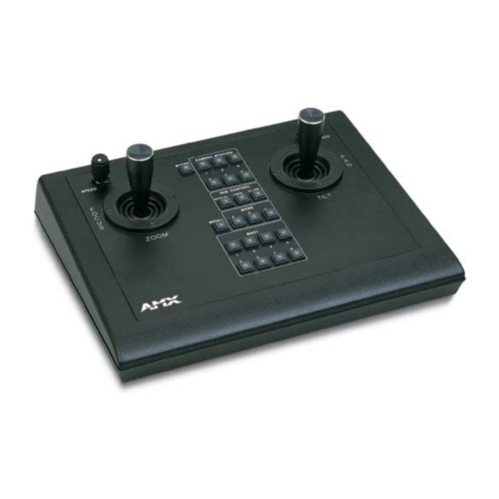
Product Information Product Information The AXP-CCS and AXM-CCS Softwire Camera Centers connect to an AMX Control System and control a wide variety of external camera equipment. Both of the camera centers are equipped with dual-axis proportional-speed joysticks with over-sized handles for precision pan, tilt, zoom, and focus control. - Page 6 Product Information AXP-CCS/AXM-CCS Softwire Camera Centers...
-
Page 7: Installation
Installation Installation The AXP-CCS and AXM-CCS contain an AXP-AI8 Analog 8-Input Board and MSP Mini- Softwire Panel that act as two AXlink devices. The factory-default setting for the AXP-AI8 is 129. The MSP addresses for the AXP-CCS and AXM-CCS are 130 and 131 respectively. -
Page 8: Verifying The Axp-Ai8 I/O Dip Switch Settings
FIG. 3 I/O DIP switch settings Mounting the AXP-CCS The AXP-CCS is a table-top configuration, and can be mounted on any flat surface. FIG. 4 shows the dimensions of the AXP-CCS. 4.00" (10.60 cm) 10.00"... -
Page 9: Wiring The Axp-Ccs And Axm-Ccs
Wiring guidelines The AXP-CCS and AXM-CCS require 12 VDC power to operate properly. The Axcess Control System supplies power via the AXlink cable or external 12 VDC power supply. The maximum wiring distance between the control system and camera centers determines power consumption, supplied voltage, and the wire gauge used for the cable. -
Page 10: Using The Axp-Ccs Mini-Xlr Connector For Axlink And An External Power Supply
Using the AXP-CCS mini-XLR connector for AXlink and an external power supply Connect the control system's AXlink connector to the mini-XLR connector and external 12 VDC power supply to the rear panel of the AXP-CCS, as shown in FIG. 7. 12 VDC power supply... -
Page 11: Programming
Programming Programming The AXP-CCS and AXM-CCS pushbuttons are programmed individually or in any combination as single devices or in a group arrangement. FIG. 10 and show the channel (push) codes for each pushbutton on AXP-CCS and AXM-CCS camera centers. Pushbutton channel (push) code FIG. -
Page 12: Pushbutton Leds
You may enter the configuration mode or toggle these functions as often required. Levels Levels are the values that are related to the analog input or output on the AXP-AI8 device in the AXP-CCS. The following table lists the levels. Levels Level Description... - Page 13 Programming AXP-CCS/AXM-CCS Softwire Camera Centers...
- Page 14 AMX reserves the right to alter specifications without notice at any time. brussels • dallas • los angeles • mexico city • philadelphia • shanghai • singapore • tampa • toronto • york 3000 research drive, richardson, TX 75082 USA • 469.624.8000 • 800.222.0193 • fax 469.624.7153 • technical support 800.932.6993...
Need help?
Do you have a question about the AXP-CCS and is the answer not in the manual?
Questions and answers