
Related Manuals for AMX AXP-CCV


Summary of Contents for AMX AXP-CCV
- Page 1 $;30&&92$;00&&9 &RORU 9LGHR &DPHUD &HQWHUV ,QVWUXFWLRQ 0DQXDO &DPHUD &RQWURO 6\VWHPV...
-
Page 2: Limited Warranty And Disclaimer
AMX dealer. Consumers should inquire from selling dealer as to the nature and extent of the dealer’s warranty, if any. AMX is not liable for any damages caused by its products or for the failure of its products to perform, including any lost profits, lost savings, incidental damages, or consequential damages. -
Page 3: Table Of Contents
Verifying AXP-AI8 I/O DIP Switch Settings Installation ................11 Overview Installing the AXP-CCV Installing the AXM-CCV Wiring the AXP-CCV and AXM-CCV Preparing captive wires Wiring guidelines Using AXP-CCV mini-XLR connector for AXlink data and power Using AXP-CCV mini-XLR connector for... - Page 4 Mini-Color Touch Panel Pages Specifications............... 27 Overview Technical Support ..............29 Overview Table of Contents AXP-CCV/AXM-CCV Color Video Camera Centers...
-
Page 5: Introduction
Introduction Overview Connected to an AMX Control System via AXlink, the AXP-CCV (Figure 1) and AXM-CCV (Figure 2) Color Video Camera Centers provide integrated, programmable control of pan/tilt heads and lenses, VCRs, video codecs, video switchers, monitors, and other equipment. Both of the camera centers combine... -
Page 6: Features
22 programmable pushbuttons equipped with LED for feedback Engraved overlay with pushbutton functions and groupings Compatibility with all AXCESS Control Systems Tabletop mounting (AXP-CCV) or rack mounting (AXM-CCV) For information about creating Touch Panel pages, refer to the Color Active-Matrix Mini-LCD Touch Panel Instruction Manual. -
Page 7: Application
What’s in this Manual This manual contains the following sections: Pre-Installation Settings Shows how to set the AXlink device numbers in the AXP-CCV and AXM-CCV. Installation Describes the installation and wiring of the AXP-CCV and AXM-CCV. AXP-CCV/AXM-CCV Color Video Camera Centers Introduction... -
Page 8: What's New
All new information, features, and operations added since the previous release of this manual are identified with vertical margin bars: Revised the information in the Setting the Touch Panel device number section. Added information and drawings to the Wiring the AXP-CCV and AXM-CCV and Specifications sections. Introduction... -
Page 9: Pre-Installation
I/O DIP switch settings in the AXP-CCV and AXM-CCV. Setting the AXlink Device Numbers Note The AXlink device number range is 1 - 255. To set the AXP-CCV and AXM-CCV You must use unique AXlink AXlink device numbers: device numbers for the AXP-... -
Page 10: Setting The Touch Panel Device Number
Mini-Touch Panel and control system. To set the device number: Ensure that a mini-XLR cable (for the AXP-CCV) or an AXlink cable (for the AXM-CCV) is connected to the rear from the control system. It is this system that is connected to a 12 VDC power supply. - Page 11 Figure 6 MAIN page Press the SETUP button and the ADJUST ATTRIBUTES page (Figure 7) appears. To access the CCV’s setup information, press PROTECTED SETUP. Figure 7 ADJUST ATTRIBUTES page AXP-CCV/AXM-CCV Color Video Camera Centers Pre-Installation...
- Page 12 Press SET DEVICE to open the device number keypad of the CCV (Figure 9) and enter a unique AXlink device number; the range is 1 through 255. Figure 9 Device number keypad CLEAR Clears the keypad number. Pre-Installation AXP-CCV/AXM-CCV Color Video Camera Centers...
-
Page 13: Verifying Axp-Ai8 I/O Dip Switch Settings
1 - 6 OFF (up) to enable joystick and speed control operation. Verify that the DIP switch settings on the AXP-CCV and AXM-CCV match the settings shown in Figure 10. Refer to Setting the AXlink Device Numbers instructions to access the AXP-AI8 board. - Page 14 Pre-Installation AXP-CCV/AXM-CCV Color Video Camera Centers...
-
Page 15: Installation
Overview This section describes the wiring and installation of the AXP-CCV and AXM-CCV Camera Centers. Since the AXP-CCV is a table-top configuration (Figure 11), it can be mounted on any flat surface, whereas the AXM-CCV can be mounted within most racks. -
Page 16: Installing The Axm-Ccv
The mini-XLR (male) cable (Figure 16) is connected from the rear of the Wiring guidelines subsection. AXB-EM232 to the rear of the AXP-CCV. Figure 17 shows another wiring option that has an auxiliary power supply wired directly into the mini-XLR cable. -
Page 17: Wiring The Axp-Ccv And Axm-Ccv
Wiring the AXP-CCV and AXM-CCV The AXP-CCV and AXM-CCV communicate with the AXCESS Control System via AXlink. The AXP-CCV contains a mini-XLR (female) connector on the rear panel for AXlink communication and a BNC (female) video connection for video input as shown in Figure 13. -
Page 18: Preparing Captive Wires
Wiring guidelines The AXP-CCV and AXM-CCV require 12 VDC power to operate properly. The AXCESS Control System supplies power via the AXlink cable or external auxiliary 12 VDC power supply. The maximum wiring distance between the control system and camera centers is determined by power consumption, supplied voltage, and the wire gauge used for the cable. -
Page 19: Using Axp-Ccv Mini-Xlr Connector For Axlink Data And Power
Using AXP-CCV mini-XLR connector for AXlink data and power Connect the control system’s AXlink connector to the mini-XLR connector (male) on the rear panel of the AXP-CCV for data and 12 VDC power as shown in Figure 16. Figure 16... -
Page 20: Using Axm-Ccv Axlink Connector For Data And Power
AXM-CCV, for data and 12 VDC power as shown in Figure 18. Figure 18 PWR+ AXlink wiring diagram Control system Caution GND - If you are using power from AXlink, disconnect the wiring AXlink connector from the control system before wiring the AXM-CCV. Installation AXP-CCV/AXM-CCV Color Video Camera Centers... -
Page 21: Using Axm-Ccv Axlink Connector For Data And An External 12 Vdc Power Supply
Do not connect the PWR wire to the AXlink connector’s PWR (+) terminal. Using a BNC video cable to provide video input Connect the control system’s video connector at the rear panel of the AXM-CCV and AXP-CCV to the video source as shown in Figure 20. BNC (female) connector Figure 20... - Page 22 Installation AXP-CCV/AXM-CCV Color Video Camera Centers...
-
Page 23: Axcess Programming
AI8 (for any one of the AXP-CCS, AXM-CCS, AXP-CCV) at #129, CPI for AXP-CCS at #130, CPI for AXM-CCS at #131, and CPI for AXP-CCV at #128. If multiple panels are needed, this will require custom code. -
Page 24: Hardware Configuration
(see Figure 26). If the lens type is wrong, typically it will operate but it will not go to a preset. Channel Assignments Channels correspond to the actual control functions. Figure 21 AXP-CCV external buttons CHANNEL CHANNEL Figure 22 lists the channel assignments for the AXP-CCV. AXCESS Programming AXP-CCV/AXM-CCV Color Video Camera Centers... -
Page 25: Levels
Levels Levels are the values that are related to the analog input or output on the AXP-AI8 device in the AXP-CCV and AXM-CCV. The program recognizes the movement of the controls through x/y coordinates. Figure 23 lists the levels. AXP-CCV/AXM-CCV Color Video Camera Centers... -
Page 26: Mini-Color Touch Panel Pages
Pan/Tilt speed Zoom/Focus speed Mini-Color Touch Panel Pages The AXM-CCV and AXP-CCV can both be loaded with an AMXAXPCC.PGT Note program, which gives you some sample touch pages (along with its associated AXCESS code). If you were to use the above .PGT file, the following page layouts You can open this file using TP 1.2 or greater. - Page 27 This screen allows you to control the aperture of the iris. Figure 26 AXP-CCV and AXM-CCV Camera A Setup Note This screen allows you to adjust the camera’s functions. This is a one-time setup. AXP-CCV/AXM-CCV Color Video Camera Centers AXCESS Programming...
- Page 28 The calibrate joystick allows you to manually calibrate the joystick. Initially, the program waits 5 seconds, then reads all the levels (Figure 23) of the AI8 and begins recalibrating. Figure 28 AXP-CCV and AXM-CCV First Help About box AXCESS Programming AXP-CCV/AXM-CCV Color Video Camera Centers...
- Page 29 Figure 29 AXP-CCV and AXM-CCV Second Help About box AXP-CCV/AXM-CCV Color Video Camera Centers AXCESS Programming...
- Page 30 AXCESS Programming AXP-CCV/AXM-CCV Color Video Camera Centers...
-
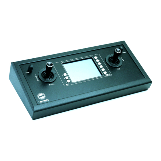
Page 31: Specifications
Specifications Overview Figure 30 shows the AXP-CCV and Figure 31 lists its specifications. Figure 32 shows the AXM-CCV and Figure 33 lists its specifications. Figure 30 AXP-CCV Camera Center (table-top configuration) Figure 31 AXP-CCV specifications AXP-CCV specifications Dimensions (HWD) 4.80" (including joysticks) x 15.50" x 7.25" (121.00 mm x 393.70 mm x 184.15 mm) - Page 32 (133.35 mm x 482.60 mm x 120.65 mm) Weight 3.80 lb (1.41 kg) Enclosure Metal with matte black finish and rack mounts Power Consumption 12 VDC 825 mA Connectors 4-pin connector (AXlink) BNC (female) Video In connector Specifications AXP-CCV/AXM-CCV Color Video Camera Centers...
-
Page 33: Technical Support
Technical Support Overview Prior to calling AMX for assistance, check your AXlink, power, and cable connections, and the integrity of your software operating system. Reload the software to see if something in the program is causing the problem. If the problem is not resolved, reload the program from a new copy of your master disk. - Page 34 048-004-1584 8/98 ©1998 AMX Corporation. All rights reserved. Dallas, Texas USA 75243 AMX and the AMX logo are registered trademarks of AMX Corporation. All other 972/644-3048 800/222-0193 trademarks contained in this document are the properties of their respective Fax 972/907-2053 www.amx.com...
Need help?
Do you have a question about the AXP-CCV and is the answer not in the manual?
Questions and answers