
Related Manuals for Allied Telesis CentreCOM AT-MR415T


Summary of Contents for Allied Telesis CentreCOM AT-MR415T
- Page 1 ® CentreCOM AT-MR415T AT-MR815T Multiport 10Base-T Micro Repeaters Installation Guide PN 613-10685-00 Rev A...
- Page 2 All rights reserved. No part of this publication may be reproduced without prior written permission from Allied Telesyn International Corp. Allied Telesyn International Corp. reserves the right to make changes in specifications and other information contained in this document without prior written notice. The information provided herein is subject to change without notice.
-
Page 3: Electrical Safety And Installation Requirements
Declares that the product: Multiport Ethernet Hub unit Model Numbers: AT-MR415T and AT-MR815T Complies with FCC Part 15B, Class B Limits: This device complies with part 15 of the FCC Rules. Operation is subject to the following two conditions: (1) This device must not cause harmful interference, and (2) this device must accept any interference received, including interference that may cause undesired operation. - Page 4 Electrical Safety and Installation Requirements STANDARDS: This product meets the following standards RFI Emission EN55022 Class B Immunity EN50082-1 SAFETY Power to the hub must be sourced only from the adapter. AUSTRALIA Use a safety approved AC adapter of DC 7.5V to 12V, min 500mA EUROPE - EC Use TÜV licensed AC adapter of DC 7.5V, 500mA.
- Page 5 AT-MR415T and AT-MR815T Installation Guide Radiofrekvens forstyrrelsesemission EN55022 Klasse B Immunitet EN50082-1 SIKKERHED Strømforsyningen til apparatet må udelukkende tages fra tilpasningstransformatoren. EUROPE - EC Brug kun TÜV godkendt vekselstrømstransformator på 7.5 V jævnstrøm, 500 mA. FARE UNDER UVEJR FARE: UNDLAD at arbejde på udstyr eller KABLER i perioder med LYNAKTIVITET.
- Page 6 Electrical Safety and Installation Requirements Radioaaltojen häirintä EN55022 Luokka B Kestävyys EN50082-1 TURVALLISUUS Tähtipisteeseen (hub) syötettävän virran pitää tulla ainoastaan sovittimesta. EUROPE - EC Käytä TÜV-lisenssillä valmistettua verkkosovitinta, jonka tasajännitteen nimellisarvot ovat DC 7,5 V, 500 mA (milliampeeria). SALAMANISKUVAARA HENGENVAARA: ÄLÄ TYÖSKENTELE laitteiden tai KAAPELEIDEN KANSSA SALAMOINNIN AIKANA.
- Page 7 AT-MR415T and AT-MR815T Installation Guide Emissão de interferência de radiofrequência EN55022 Classe B Imunidade EN50082-1 SEGURANÇA Use somente o adaptador fornecido para alimentação elétrica do hub. EUROPE - EC Use um adaptador de corrente alternada com saída DC de 7,5V e 500mA em conformidade com as especificações da TÜV.
-
Page 9: Table Of Contents
Package Contents ....................2 Latest Technologies .....................2 ASIC/SMT.....................2 Packet Regeneration ..................2 Link Integrity ....................2 Auto Partitioning ..................2 Jabber Lock-up Protection ................3 AT-MR415T ......................3 Light Emitting Diodes (LEDs)..............3 AT-MR815T ......................5 Light Emitting Diodes (LEDs)..............5 Chapter 2 Installation .......................9 Site Requirements ....................9 Ventilation ....................9 Power ......................9... - Page 10 5 - 4 - 3 Rule ...................... 27 Appendix B Glossary ......................29 Appendix C Technical Support Fax Order ..............35 Incident Summary .................... 35 Appendix D AT-MR415T/AT-MR815T Installation Guide Feedback ....... 37 Appendix E Where To Find Us ..................39...
-
Page 11: Chapter 1 Product Description
IEEE standards. While identical in structure, the AT-MR415T Micro Repeater differs from the AT-MR815T Micro Repeater in that the former has four (4) Unshielded Twisted Pair (UTP) ports whereas the latter has eight (8). -
Page 12: Package Contents
Four (4) Rubber feet for desktop placement Latest Technologies ASIC/SMT AT-MR415T/AT-MR815T Micro Repeaters have incorporated the latest technologies, including custom Application Specific Integrated Circuit (ASIC) and Surface Mount Technology (SMT). This results in enhanced functionality, increased reliability and improved performance. -
Page 13: Jabber Lock-Up Protection
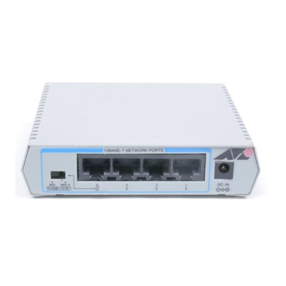
(usually 5 ms). AT-MR415T Figure 1 shows the front panel of an AT-MR415T. Figure 1: AT-MR415T Front Panel Light Emitting Diodes (LEDs) Four Link LEDs show the connectivity of each network port. Three additional LEDs indicate Activity, Collision and Power for the repeater itself. - Page 14 — This LED lights when power is being received by the repeater from the AC to DC adapter. Figure 2 shows the back panel of an AT-MR415T. Figure 2: AT-MR415T Back Panel Four UTP RJ45 network ports (including Port 4, an uplink port) are located on the back panel.
-
Page 15: At-Mr815T
AT-MR415T and AT-MR815T Installation Guide MDI MDI-X Toggle Switch — This switch allows you to set the cascade port (the port directly to the right of this switch). This cascade port, in turn, can be used to either connect to another repeater or as a normal 10Base-T port. - Page 16 Product Description In other words, the LED is lighted anytime a valid communications link has been established for the corresponding port. If the LED is not lighted, check the twisted pair cable to ensure a proper port connection has been made. ACTIVITY lamp (green) —...
- Page 17 AT-MR415T and AT-MR815T Installation Guide MDI MDI-X Toggle Switch — This switch allows you to set the cascade port (the port directly to the right of this switch). The cascade port, in turn, can be used to either connect to another repeater or as a normal 10Base-T port.
-
Page 19: Chapter 2 Installation
Installation Site Requirements Ventilation AT-MR415T/AT-MR815T Micro Repeaters have openings on both sides for ventilation. Although these Micro Repeaters do not require an internal fan to aid in cooling, adequate ventilation is required. Ensure that the ventilation openings located on the sides of the chassis are never blocked. -
Page 20: Utp (Rj-45) Connectivity
Installation Table 1 shows the model variations and different power arrangements for AT-MR415T/AT-MR815T Micro Repeaters: Table 1: Model Configurations Model Location Voltage AT-MR415T-10 North America 90/120 VAC AT-MR815T-10 North America 90/120 VAC AT-MR415T-20 Europe/Asia 200/240 VAC AT-MR815T-20 Europe/Asia 200/240 VAC... -
Page 21: 10Base-T Cable
AT-MR415T and AT-MR815T Installation Guide 10Base-T Cable The AT-MR415T/AT-MR815T Micro Repeater supports full-length, fully repeated transmission and maximum node attachments which, for the UTP link, enables transmissions up to 100 meters (328 ft.). A serious problem exists concerning identification of modular cable. There are various grades of voice-quality and data-quality cables available. -
Page 22: Quick Installation
Installation Hub to MAU Wiring. The most typical UTP cable for the AT-MR415T/ AT-MR815T Micro Repeater will be UTP Hub-to-UTP transceiver Data Terminal Equipment (DTE). To configure your own cables, see Appendix A, “Technical Specifications” on page 23. Quick Installation If you are experienced with electronic networks in general and repeaters in particular, use the following procedure. -
Page 23: 10Base-T Network Specifications
AT-MR415T and AT-MR815T Installation Guide 10Base-T Network Specifications Table 3 provides an overview of the IEEE 802.3 specifications for 10Base-T network configurations using twisted-pair wiring. Table 3: IEEE 802.3 Network Specifications 10Base-T Media Unshielded Twisted Pair Topology Star, Tree External Devices... -
Page 24: Standalone Placement Of The Mr415T/Mr815T
Attach the four rubber feet provided with the unit to the underside of the device in the four corners. Figure 6 shows how the rubber feet are attached to an AT-MR415T. Figure 6: AT-MR415T Horizontal Mounting Connecting to a Network 1. - Page 25 6. Perform the following to cascade two AT-MR415T/AT-MR815T Micro Repeaters together: Port 4 of the AT-MR415T and port 8 of the AT-MR815T are designed to allow HUBs to be cascaded together (cascade port). To cascade an AT-MR415T/AT-MR815T Micro Repeater with an existing device, select...
-
Page 26: Examples Of Network Connections
Installation Examples of Network Connections A Local Area Network can be constructed as shown in Figure 7. Figure 7: LAN Connectivity A Local Area Network can be expanded as shown Figure 8. MDI-X MDI-X to HUB to HUB to PC to PC Figure 8: LAN Expansion... - Page 27 AT-MR415T and AT-MR815T Installation Guide Note Regardless of your current network configuration, the maximum number of AT-MR415T/AT-MR815T Micro Repeaters which can be cascaded together is four. Before expanding a network through a T-port, consult the network administrator. Be sure that the expansion will not exceed the limit defined by the current LAN configuration before proceeding.
- Page 28 Installation Invalid Cascading. An example of invalid cascading is shown in Figure 10. When sending packets over the network, it is possible to send information through up to four cascaded repeaters; however, five or more cascaded repeaters will not produce guaranteed results. Referring to Figure 10, there are four repeaters between PC A and PC B so the connection between PC A and PC B is possible;...
-
Page 29: Chapter 3 Troubleshooting
PC A Figure 11: AT-MR815T Connection Test 1. Connect port 1 and port 2 of a single AT-MR415T/AT-MR815T Micro Repeater to two computers and turn on the HUB power supply by connecting the AC adapter. (In Figure 11 above, PC B is connected to port 1 and PC A is connected to port 2.) -
Page 30: Troubleshooting
5. Verify the connection in each port by checking the LINK ON lamp and performing the communications test as described in steps 2 and 3. 6. Once each port of a single AT-MR415T/AT-MR815T Micro Repeater has been tested, check the connection between computers of two different repeaters (if your configuration has more than one repeater). -
Page 31: Is The Link On Lamp Lighted
MDI, while the other unit should have its switch set to MDI-X. When port 4 of the AT-MR415T or port 8 of the AT-MR815T are not connected to another repeater, but are used to connect to a computer or... -
Page 33: Technical Specifications
Appendix A Technical Specifications AT-MR415T Physical Width 112 mm (4.48 in.) Height 98 mm (3.92 in.) Depth 26 mm (1.04 in.) Weight 280 g (9.9 oz.) Installation options Tabletop or rack-mount Connector Ports 10Base-T RJ-45 Ethernet ports AT-MR815T Physical Width 175 mm (7 in.) -
Page 34: At-Mr415T/At-Mr815T
Technical Specifications AT-MR415T/AT-MR815T Electrical Use only the wall mounted adapter provided with the product. Countries/Power Voltage Frequency Australia 240VAC 50Hz United Kingdom 240VAC 50Hz Common Market (EC) 230VAC 50Hz (except UK) North America 120VAC 60Hz Maximum Power Consumption 12 Watts Input current 0.5 A (500 mA) Maximum... -
Page 35: 10Base-T Pin Assignments
AT-MR415T and AT-MR815T Installation Guide 10Base-T Pin Assignments An Ethernet twisted-pair link segment requires two pairs of wires. Each wire pair is identified by solid and striped colored wires. For example, one wire in the pair might be red and the other wire, red with white stripes. -
Page 36: Straight-Through Wiring
6 (RX-) Crossover Wiring Two AT-MR415T/AT-MR815T Micro Repeaters can communicate only if the transmitter on one unit is connected to the receiver on the other unit. This reversal, or crossover function, can be implemented either in the wiring or in the device itself. -
Page 37: 5 - 4 - 3 Rule
AT-MR415T and AT-MR815T Installation Guide 5 - 4 - 3 Rule In addition to IEEE requirements, Table 4 and Table 5, follow the “5-4-3 rule” to ensure that your configuration does not exceed the maximum 10Base-T data transmission path (the longest path through any given network). -
Page 39: Appendix B Glossary
Appendix B Glossary 10Base-T—IEEE 802.3 UTP Ethernet. Low-cost Level 3 or better UTP wiring affords 100 meters (328 ft.) of point-to-point link segments. UTP uses RJ-45 connectors and sometimes 50-pin AMP connectors to a patch panel and runs at 10 MHz. BASEBAND COAXIAL SYSTEM—A system whereby information is directly encoded and impressed on the coaxial transmission medium. - Page 40 Glossary CROSSOVER—Wiring used when connecting a 10Base-T MAU to another 10Base-T MAU or a 10Base-T hub to another 10Base-T hub. For example, one 10Base-T MAU has the TD pair on the same pins as another 10Base-T MAU. If pins were wired straight, there would be two transmitters on one pair and no receiver.
- Page 41 AT-MR415T and AT-MR815T Installation Guide JAM—This is a term used to describe the collision reinforcement signal output by the repeater to all ports. The jam signal consists of 96 bits of alternating 1s and 0s. The purpose is to extend a collision sufficiently so that all devices cease transmitting.
- Page 42 Glossary MANAGEMENT INFORMATION BASE (MIB)—A data base of network configuration and performance information. The formal definition of a MIB includes the names of the objects it contains and the type of information retained. Management protocols such as SNMP and CMIP contain procedures for acquiring and exchanging MIB information.
- Page 43 AT-MR415T and AT-MR815T Installation Guide SIGNAL QUALITY ERROR (SQE) TEST—Signal indicates SQE function is active. The SQE message is sent by the MAU to the DTE in the presence of a collision. SIMPLE NETWORK MANAGEMENT PROTOCOL (SNMP)— SNMP is a...
-
Page 45: Technical Support Fax Order
Appendix C Technical Support Fax Order Name__________________________________________________________________ Company _______________________________________________________________ Address ________________________________________________________________ City ________________________ State/Province_______________________________ Zip/Postal Code ___________________ Country_______________________________ Phone _______________________________ Fax _______________________________ Incident Summary Model number of Allied Telesyn product I am using _____________________________ Firmware release number of Allied Telesyn product _____________________________ Other network software products I am using (e.g., network managers) ______________________________________________________________________ ______________________________________________________________________... -
Page 47: At-Mr415T/At-Mr815T Installation Guide Feedback
Appendix D AT-MR415T/AT-MR815T Installation Guide Feedback Please tell us what additional information you would like to see discussed in this guide. If there are topics you would like information on that were not covered in this guide, please photocopy this page, answer the questions and fax or mail this form back to Allied Telesyn. -
Page 49: Appendix E Where To Find Us
Address: gateway.centre.com [lowercase letters] Login: anonymous [lowercase letters] Password: your e-mail address [requested by the server at login] For Information Regarding Allied Telesyn International Corp. Allied Telesyn International Corp. Allied Telesyn International Corp. 19015 North Creek Parkway 950 Kifer Road... - Page 50 Where To Find Us For Sales Information Australia San Diego, CA Tel: (619) 279-3899, Fax: (619) 279-3897 Lindfield, NSW Tel: (612) 416-0619, Fax: (612) 416-9764 Santa Ana, CA Tel: (714) 838-0434, Fax: (714) 838-9721 Canada Clearwater, FL Rexdale, Ontario Tel: (813) 726-0022, Fax: (813) 726-0234 Tel: (416) 675-6738, Fax: (416) 675-0057 Norcross, GA Richmond, British Columbia...
- Page 51 Index Alternating Current (AC) adapter 4, IEEE 802.3 specifications 13 impedance 10 application specific integrated circuit indicators (ASIC) 2 activity 3, 5 collision 3, 5 cables 10 link 3, 5 cabling link ok 13 10Base-T 12, 13 power 3, 5 5 - 4 - 3 rule 27 installation 9 power 9...
- Page 52 Index rubber feet 14 segmentation 2 signal propagation delays 15 site requirements 9 specifications 10Base-T Network 13 certification 24 connector ports 23 diagnostic LEDs 24 electrical 24 environmental 24 physical 23 surface mount technology (SMT) 2 valid connection 19 valid link 3 ventilation 9 wiring 11, 12, 13, 25, 26, 27...
Need help?
Do you have a question about the CentreCOM AT-MR415T and is the answer not in the manual?
Questions and answers