Table of Contents
Advertisement
Quick Links
Advertisement
Table of Contents

Related Manuals for Allied Telesis CentreCOM AT-MR118FT


Summary of Contents for Allied Telesis CentreCOM AT-MR118FT
- Page 1 Allied Telesyn CentreCOM™ AT-MR118FT AT-MR128FT Micro Repeaters User Manual...
- Page 2 © Copyright 1994 Allied Telesyn International Corp. All rights reserved. No part of this publication may be reproduced without prior written permission from Allied Telesyn International Corp. Allied Telesyn International Corp. reserves the right to make changes in specifications and other information contained in this document without prior written notice.
- Page 3 RADIATED ENERGY U.S. Federal Communications Note: This equipment has been tested and found to comply with the limits for a Class A digital device pursuant to Part 15 of FCC Rules. These limits are designed to provide Electrical Safety and Installation reasonable protection against harmful interference when the equipment is operated in a commercial environment.
- Page 4 SICHERHEIT ACHTUNG: GEFÄHRLICHE SPANNUNG Das Gehäuse nicht öffnen. Das Gerät enthält keine vom Benutzer wartbaren Teile. Das Gerät steht unter Hochspannung und darf nur von qualifiziertem technischem Personal geöffnet werden. Vor Anschluß der LAN-Kabel, Gerät vom Netz trennen. GEFAHR DURCH BLITZSCHLAG GEFAHR: Keine Arbeiten am Gerät oder an den Kabeln während eines Gewitters ausführen VORSICHT:DAS NETZKABEL DIENT ZUM TRENNEN DER...
- Page 5 ELEKTRISK—LEDNING Anvend ledning af maksimum 4.5 meters længde, med en kapacitet på minimum 6 amp, 250 v, bestående af en IEC 320 connector med indstøbt HAR ledning i den ene ende og et stik i den anden ende godkendt der er af myndighederne i brugerlandet. ADVARSEL: Ventilationsåbninger må...
- Page 6 ENERGIE RAYONNEE Ce matériel a été testé et est certifié conforme par la réglementation américaine aux normes définies pour les appareils de classe A. SECURITE INFORMATION SUR L’ELECTRICITE AVERTISSEMENT: DANGER D’ELECTROCUTION Pour empêcher les dangers d’ELECTROCUTION, ne pas enlever le couvercle. L’équipement ne contient aucun élément réparable par l’utilisateur.
- Page 7 HUOMAUTUS: VIRTAJOHTOA KÄYTETÄÄN VIRRANKATKAISULAITTEENA. VIRTA KATKAISTAAN irrottamalla virtajohto. ASENNUS SÄHKÖ —AUTOMAATTINEN JÄNNITTEENSÄÄTÖ Tämä tuote säätää automaattisesti mihin tahansa jännitteeseen ohjetarrassa annettujen arvojen välillä. SÄHKÖ —TYYPPILUOKAN 1 LAITTEET TÄMÄ LAITE TÄYTYY MAADOITTAA. Pistoke täytyy liittää kunnollisesti maadoitettuun pistorasiaan. Virheellisesti johdotettu pistorasia voi altistaa metalliosat vaarallisille jännitteille.
- Page 8 TEMPERATURA DI FUNZIONAMENTO Questo prodotto è concepito per una temperatura ambientale massima di 50 gradi centigradi. TUTTI I PAESI: installare il prodotto in conformità alle vigenti normative elettriche nazionali. UTSTRÅLT ENERGI Dette kommersielle produktet har blitt testet og er i samsvar med amerikanske krav for et A-Klasse apparat.
- Page 9 CUIDADO: O CABO DE ALIMENTAÇÃO É UTILIZADO COMO UM DISPOSITIVO DE DESCONEXÃO.PARA DESELETRIFICAR O EQUIPAMENTO desconecte o cabo de alimentação. INSTALAÇÃO ELÉTRICO—AJUSTE AUTOMÁTICO DE VOLTAGEM Este produto ajustar-se-á automaticamente a qualquer voltagem que esteja dentro dos limites indicados no rótulo. ELÉTRICO—EQUIPAMENTOS DO TIPO CLASSE 1 DEVE SER FEITA LIGAÇÃO DE FIO TERRA PARA ESTE EQUIPAMENTO.
- Page 10 TEMPERATURA REQUERIDA PARA LA OPERACIÓN Este producto está diseñado para una temperatura ambiental máxima de 50 grados C. PARA TODOS LOS PAÍSES: Monte el producto de acuerdo con los Códigos Eléctricos locales y nacionales. ENERGIUTSTRÅLNING Denna handelsprodukt har testats och befunnits vara i enlighet med U.S.A.s krav för klass A utrustning.
-
Page 11: Table Of Contents
List of Figures List of Figures Figure 1: AT-MR118FT Front and Back Panels 8 Figure 2: AT-MR128FT Front and Back Panels 9 Figure 3: Typical Hub Configuration 11 Figure 4: 10BASE-T UTP Cabling Hub to MAU or NIC (Straight-Through) 19 Figure 5: 10BASE-T UTP Cabling Hub to Hub (Cross-Over) 19 Figure 6: Hub to MAU Wiring A.Usable and B. - Page 12 List of Tables List of Tables Table 1: The AT-MR118FT and AT-MR128FT Characteristics 1 Table 2: CentreCOM Micro Repeater Dimensions 2 Table 3: Usable and Unusable Twisted Pair Cable 18 Table 4: MDI/MDI-X Switch Settings for Common Connection 20...
- Page 13 Table of Contents Electrical Safety and Installation Requirements ........iii List of Figures ......................i List of Tables ....................... i Chapter 1 Overview ........................1 CentreCOM Fiber Optic to 10BASE-T Micro Repeaters .........1 Dimensions of Internal and External Micro Repeaters..........2 Full- and Half-Repeater Modes ..................2 Connector Types ......................3 Power Requirements.......................3 External Power Supply Micro Repeaters............3...
-
Page 14: List Of Figures
Glossary ........................25 Technical Support Fax Order ................31 CentreCOM AT-MR118FT and AT-MR128FT Manual Feedback ..33 Index ..........................35 List of Figures Figure 1: AT-MR118FT Front and Back Panels ..........8 Figure 2: AT-MR128FT Front and Back Panels ..........8 Figure 3: Typical Hub Configuration ............. -
Page 15: Overview
Chapter 1 Overview CentreCOM Fiber Optic to 10BASE-T Micro Repeaters The AT-MR118FT and AT-MR128FT are fiber optic to Unshielded Twisted Pair (UTP) micro repeaters. The AT-MR118FT has an external power supply while the AT-MR128FT has an internal power supply. Both of these repeaters are two-port media converters designed for connections to a Fiber Optic (10BASE-FL) or Fiber Optic Inter-Repeater Link (FOIRL) segment and a UTP (10BASE-T) segment. -
Page 16: Dimensions Of Internal And External Micro Repeaters
Overview Dimensions of Internal and External Micro Repeaters The primary difference between the AT-MR118FT and the AT-MR128FT repeaters is that the AT-MR128FT is a larger repeater because both the repeater and the power supply reside together in one chassis. The dimensions of the two repeaters are shown below in Table 2. -
Page 17: Connector Types
CentreCOM™ Micro Repeaters The UTP-to-fiber optic port transmission needs to be regenerated by Note the PRC to ensure integrity of timing. Because the UTP-to-fiber optic transmission is routed through a regenerating chip, it uses the full- repeater strategy and does not provide the repeater count reduction benefit associated with the half-repeater strategy. -
Page 18: Chapter 2 Cabling
Chapter 2 Cabling Two types of cabling exist for the AT-MR118FT and AT-MR128FT. They are: UTP (10BASE-T) Fiber Optic (10BASE-FL/FOIRL) The 10BASE-T cabling type is UTP while 10BASE-FL and FOIRL is fiber optic with FL covering a greater distance than FOIRL. Both cabling types have IEEE 802.3 specifications and limits associated with them. -
Page 19: Foirl Or 10Base-Fl Fiber Optic Connections
Cabling FOIRL or 10BASE-FL Fiber Optic Connections Warning Hazardous light emissions may exist in fiber optic systems. Severe eye damage may result if precautions are not taken. Never look into a transmitting fiber optic device, transceiver, repeater or cable. The IEEE 802.3 10BASE-FL port supports up to 2,000 meters (6,560 ft.) of multimode duplex fiber optic cable in a point-to-point link which directly attaches two devices. -
Page 20: Chapter 3 Operation
Chapter 3 Operation The AT-MR118FT and AT-MR128FT repeaters both retime and regenerate the Ethernet signal symmetry and regenerate the packet preamble. The micro repeaters also count the number of consecutive collisions. If this number reaches 32, then the repeater will take the segment Off Line (partition) to prevent a total network failure. -
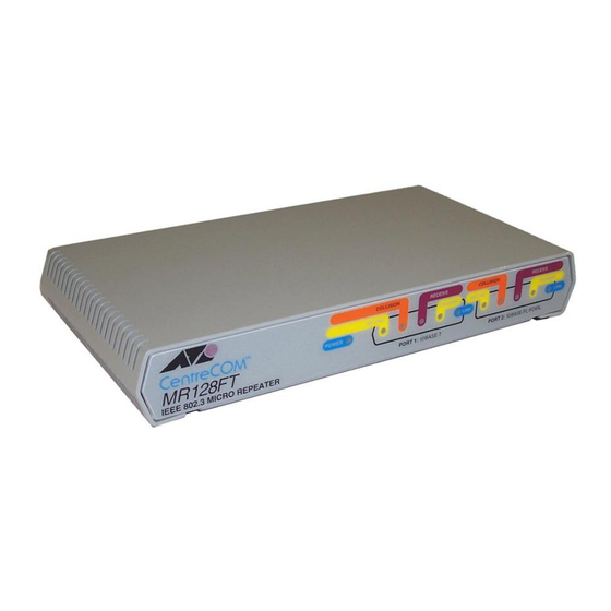
Page 21: Figure 1: At-Mr118Ft Front And Back Panels
Operation Link—Indicates when a valid link is detected by the receiver. The fiber optic Link indicator must be illuminated at both ends of the segment for Ethernet data to flow. Figure 1 and Figure 2 show the indicators and ports for both the AT-MR118FT and AT-MR128FT micro repeaters. - Page 22 CentreCOM™ Micro Repeaters To set up the sample configuration 1. Plug in the power cords to a power outlet for all devices. 2. Use either a cross-over or straight-through cable to connect your AUI/UTP hub to the AT-MR118FT UTP port. If you are using a cross-over cable, change the position of the straight-through /cross-over selection switch on the AT-MR118FT to Media Dependent Interface–cross-over (MDI-X) so that the hub-repeater connection can occur.
-
Page 23: Figure 3: Typical Hub Configuration
Chapter 4 Configuration The configuration in Figure 3 demonstrates how the AT-MR118FT and AT-MR128FT can be used to link two networks. In this scenario, two buildings are linked by fiber optic cabling and the signals are distributed by UTP. This technique takes advantage of the stronger fiber optic signal and the less expensive UTP signal technique. -
Page 24: Chapter 5 Troubleshooting
Chapter 5 Troubleshooting Experiment with Possible Solutions This chapter provides the common factors to check for troubleshooting. The first rule of troubleshooting is to isolate the problem. As you experiment, only vary one factor at a time. Substitute known good equipment and see if the problem persists or is eliminated. - Page 25 Troubleshooting On a fiber optic segment, if the Link indicator is not illuminated or data packet traffic is disrupted 1. Check that the fiber optic Link indicator is illuminated on both ends of the fiber optic link. 2. Be sure the receive fiber is connected to the remote transmit port and the transmit fiber is connected to the remote receive port.
- Page 26 CentreCOM™ Micro Repeaters 2. Use only UTP cable designed for use in 10BASE-T applications. 10BASE-T wiring lengths should not exceed 100 meters (328 ft.). The wiring should be routed away from devices known to emit electromagnetic interference, such as fluorescent lights, power transformers and relay equipment. If you have throughput problems 1.
-
Page 27: Data Cabling Techniques
Appendix A Data Cabling Techniques The following sections detail cabling techniques and port specifications for IEEE 802.3 media. For comprehensive treatment of these topics, refer to the original IEEE specification. 10BASE-T A serious problem exists concerning identification of modular cable. There are various grades of voice-quality and data-quality cables available. -
Page 28: Utp Port Wiring
Data Cabling Techniques The five common modular cable specifications and their applicability to 10BASE-T network use are shown in Table 3. Table 3: Usable and Unusable Twisted Pair Cable Cable Cable Twist/ 10BASE-T AC Character Specification Level Description Foot Unshielded CCITT None Untwisted... -
Page 29: Figure 4: 10Base-T Utp Cabling Hub To Mau Or Nic (Straight-Through)
CentreCOM™ Micro Repeaters UTP HUB UTP MAU RJ45 PIN RJ45 PIN TD + TD + TD - TD - RD + RD + Not Used Not Used Not Used Not Used RD - RD - Not Used Not Used Not Used Not Used Figure 4: 10BASE-T UTP Cabling Hub-to-MAU or NIC (Straight-Through) Some situations require a DCE-to-DCE connection, for example when hubs are... - Page 30 Data Cabling Techniques The interface type that IEEE specifies as standard for a repeater such Note as the AT-MR1x8FT is MDI-X. The straight-through/cross-over switch merely provides convenience to avoid having to obtain an alternate cable in some applications. If you connect a cable and it does not work, try changing the MDI switch.
-
Page 31: Figure 6: Hub To Mau Wiring
CentreCOM™ Micro Repeaters In both the cross-over and straight-through instances, the wire is twisted pair. Figure 6 demonstrates usable and unusable cable configurations for the straight- through wire pairing in the UTP environment. Pair twisted as per Level 3, 4 or 5 cable. RJ45 Pin RJ45 Pin Not Used... -
Page 32: Figure 7: Pin 1 Orientation On An Rj45 Connector
Data Cabling Techniques On an RJ45 connector, it is important to know where pin 1 is so you can count your pins correctly. Figure 7 shows the location of pin 1. Pin 1 Figure 7: Pin 1 Orientation on an RJ45 Connector 10BASE-FL/FOIRL Ethernet The IEEE 802.3 10BASE-FL standard supports up to 2,000 meters (6,560 ft.) of multimode duplex fiber optic cable in a point-to-point link which directly attaches... -
Page 33: 10Base2 (Thin) Ethernet
CentreCOM™ Micro Repeaters 10BASE2 (Thin) Ethernet When configuring thin coax segments, IEEE 802.3 specifications allow 29 or fewer MAUs per cable segment spaced at no less than 0.5 meter (1.64 ft.). The 10BASE2 cable length can not exceed 185 meters (607 ft.) per 10BASE2 cable segment. The worst case propagation delay for a 185 meters (607 ft.) thin Ethernet segment is 950.9 ns. - Page 34 Appendix B Glossary 10BASE2—Also called thinnet or CheaperNet, 10BASE2 is a 10 MHz, baseband, 185 meters (607 ft.) maximum coaxial segment. Cable impedance is 50 Ω. 10BASE5—Also called thick Ethernet, 10BASE5 is a 10 MHz, baseband, 500 meters (1,640 ft.) maximum coaxial segment. The cable is commonly referred to as yellow cable.
- Page 35 Glossary BIT TIME—The duration of one bit symbol (1/BR). Ethernet specifies a bit time of 100 ns. COAX SEGMENT—A segment of Ethernet cable that contains MAU. CARRIER SENSE MULTIPLE ACCESS with COLLISION DETECT (CSMA/CD)—This is the access method employed by IEEE 802.3 LAN transceivers, by which multiple stations compete for use of the transmission medium (coax cable) for data packet transmission, and provides for a level of error detection should that transmission be corrupted or impeded by contention for the...
- Page 36 CentreCOM™ Micro Repeaters DEPARTMENT CONCENTRATOR—Hub which provides a large number of workstation connections. The term, department concentrator, refers to multiple repeaters housed in an AT-36C8 chassis. See Hub/Repeater, Repeater. DIX CONNECTOR—See D-Sub Connector FOIRL — A fiber optic standard that allows up to 1,000 meters (3,280 ft.) of multimode duplex fiber optic cable in a point-to-point link.
- Page 37 Glossary LINK TEST—In 10BASE-T Ethernet there is a link test function that validates the UTP link. This consists of a pulse transmitted from point A on one pair and validated at point B. Point B also transmits a pulse on the second pair to be validated by point A.
- Page 38 CentreCOM™ Micro Repeaters PROPAGATION DELAY—The time it takes a signal to travel from the input of a system component to the output. Usually measured in nanoseconds. IEEE 802.3 has specific propagation delay maximums for computing propagation budgets when designing a LAN. Cable length plays a major role in propagation delay. [i.e, a 50 meters (164 ft.) AUI cable has a maximum allowable propagation delay of 257 ns.] The propagation delay of cable is dependent on length and velocity factor of the cable type.
- Page 39 Appendix C Technical Support Fax Order Name___________________________________________________________ Company ________________________________________________________ Address _________________________________________________________ City ____________________ State/Province ____________________________ Zip/Postal Code _______________ Country ____________________________ Phone ___________________________ Fax ____________________________ Incident Summary Model number of Allied Telesyn product I am using ______________________ Network software products I am using (e.g., network managers)____________ _______________________________________________________________ Brief summary of problem __________________________________________ _______________________________________________________________...
- Page 40 Appendix D CentreCOM AT-MR118FT and AT-MR128FT Manual Feedback Please tell us what additional information you would like to see discussed in the manual. If there are topics you would like information on that were not covered in the manual, please photocopy this page, answer the questions and fax or mail this form back to Allied Telesyn.
- Page 41 Index coaxial cable 26 adapters coaxial cable segment 26 harmonica 27 collision 26 collision presence 26 Telco 50-pin/RJ45 27 American Wire Gauge (AWG) 5 compatibility interface 26 Application Specific Integrated compliance Circuit (ASIC) 1 four repeater rule 2 Attachment Unit Interface (AUI) 8 IEEE 802.3 6 AUI 9, 22, 25 IEEE 802.3 specification 1, 5...
- Page 42 Index Ethernet 1, 5, 7, 22 Packet Retiming Controller (PRC) 2 patch panel 28 PLS 28 fiber optic 2, 5, 6, 9 PMA 28 duplex cable 6 polarity correction 28 power requirements 3 external power supply 1, 2, 3 harmonica adapter 27 internal power supply 1, 3 heartbeat 27 PRC 3...
- Page 43 Index cross-over UTP 26, 28 UTP 2, 3, 8, 9, 29 drop cable 25 Unshielded Twisted Pair (UTP) 1 fiber optic 1, 9 house wiring 27 hub to MAU UTP 27 wiring 1, 3, 5, 6, 8, 9, 23 MAU to MAU UTP 26, 28 10BASE2 25 patch panel 28 10BASE5 25...
Need help?
Do you have a question about the CentreCOM AT-MR118FT and is the answer not in the manual?
Questions and answers