
Related Manuals for Allied Telesis AT-3012SL


Summary of Contents for Allied Telesis AT-3012SL
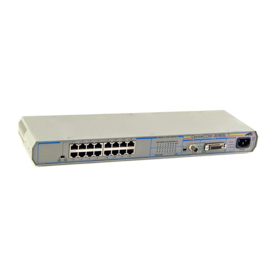
- Page 1 ® CentreCOM AT-3012SL AT-3016SL AT-3024SL Multiport Repeaters Installation Guide PN 613-10627-00 Rev A...
- Page 2 © Copyright 1997 Allied Telesyn International Corp. All rights reserved. No part of this publication may be reproduced without prior written permission from Allied Telesyn International Corp. Allied Telesyn reserves the right to make changes in specifications and other information contained in this document without prior written notice.
-
Page 3: Electrical Safety And Installation Requirements
Electrical Safety and Installation Requirements STANDARDS : This product meets the following standards U.S. Federal Communications Commission RADIATED ENERGY Note: This equipment has been tested and found to comply with the limits for a Class A digital device pursuant to Part 15 of the FCC Rules. These limits are designed to provide reasonable protection against harmful interference when the equipment is operated in a commercial environment. - Page 4 NORMEN : Dieses Produkt erfüllt die Anforderungen der nachfolgenden Normen. Hochfrequenzstörung EN55022 Klasse A WARNUNG : Bei Verwendung zu Hause kann dieses Produkt Funkstörungen hervorrufen. In diesem Fall müßte der Anwender angemessene Gegenmaßnahmen ergreifen. Störsicherheit EN50082-1 Elektrische Sicherheit EN60950, UL1950, CSA 950 SICHERHEIT ACHTUNG: GEFÄHRLICHE SPANNUNG Das Gehäuse nicht öffnen.
- Page 5 EISEN : Dit product voldoet aan de volgende eisen. RFI Emissie EN55022 Klasse A WAARSCHUWING : Binnenshuis kan dit product radiostoring veroorzaken, in welk geval de gebruiker verplicht kan worden om gepaste maatregelen te nemen. Immuniteit EN50082-1 Electrische Veiligheid EN60950, UL1950, CSA 950 VEILIGHEID WAARSCHUWINGEN MET BETREKKING TOT ELEKTRICITEIT WAARSCHUWING : GEVAAR VOOR ELEKTRISCHE SCHOKKEN...
- Page 6 STANDARDIT : Tämä tuote on seuraavien standardien mukainen. Radioaaltojen häirintä EN55022 Luokka A VAROITUS : Kotiolosuhteissa tämä laite voi aiheuttaa radioaaltojen häiröitä, missä tapauksessa laitteen käyttäjän on mahdollisesti ryhdyttävä tarpeellisiin toimenpiteisiin. Kestävyys EN50082-1 Sähköturvallisuus EN60950, UL1950, CSA 950 TURVALLISUUS SÄHKÖÖN LIITTYVIÄ HUOMAUTUKSIA VAROITUS : SÄHKÖISKUVAARA Estääksesi SÄHKÖISKUN älä...
- Page 7 SIKKERHETSNORMER : Dette produktet tilfredsstiller følgende sikkerhetsnormer. RFI stråling EN55022 Klasse A ADVARSEL : Hvis dette produktet benyttes til privat bruk, kan produktet forårsake radioforstyrrelse. Hvis dette skjer, må brukeren ta de nødvendige forholdsregler. Immunitet EN50082-1 Elektrisk sikkerhet EN60950, UL1950, CSA 950 SIKKERHET ELEKTRISKE MEDDELELSE ADVARSEL: FARE FOR ELEKTRISK SJOKK...
- Page 8 ESTÁNDARES : Este producto cumple con los siguientes estándares. Emisión RFI EN55022 Clase A ADVERTENCIA : en un entorno doméstico, este producto puede causar radiointerferencias, en cuyo caso, puede requerirse del usuario que tome las medidas que sean convenientes al respecto. Inmunidad EN50082-1 Seguridad eléctrica EN60950, UL1950, CSA 950 ENERGIA RADIADA...
- Page 9 ELEKTRISKT—ANMÄRKNING BETRÄFFANDE KABELN Använd en kabel med maximum längd 4,5 meter och minimum 6 amp nominal, 250V, av HAR kabelfabrikat med ett specialutformat IEC 320-kontaktdon i ena änden och i den andra en plugg som godkänts i landet där produkten används. VARNING : Luftventilerna får ej blockeras och måste ha fri tillgång till omgivande rumsluft för avsvalning.
-
Page 11: Table Of Contents
Table of Contents Electrical Safety and Installation Requirements ..........iii Chapter 1 Description . - Page 12 Appendix A Data Cabling Connections ..............19 10Base-T.
-
Page 13: Chapter 1 Description
(thick or thinnet coaxial, fiber optic, and twisted pair), using an external transceiver. The AT-3012SL, AT-3016SL and AT-3024SL Multiport Repeaters use the latest technologies, including a custom Application Specific Integrated Circuit (ASIC), and Surface Mount Technology (SMT). Using these technologies help enhance functionality, increase reliability, and improve price and performance. -
Page 14: Major Features
Description Major Features The major features of the AT-3012SL, AT-3016SL, and AT-3024SL Multiport Repeaters are the following: Packet Regeneration — This feature regenerates the packet preamble, retimes the data packets, and extends collision fragments. Link Integrity — The IEEE 802.3 defined link integrity test function continually monitors the twisted pair cable to ensure link continuity of the receive pair between the user node and the repeater. -
Page 15: Front Panel
RECEIVING POWER 8 16 32 64 84+% ACTIVITY MDI-X COLLISION TERMINATOR RECEIVING LINK PARTITION PARTITION POWER Figure 1: AT-3012SL Front Panel 10BASE-T PORT ACTIVITY NETWORK UTILIZATION(%) STATUS 8 16 32 64 84+% POWER RECEIVING RECEIVING ACTIVITY MDI-X COLLISION RECEIVING LINK... -
Page 16: Leds
LINK PARTITION PARTITION POWER Figure 3: 3024SL Front Panel LEDs Table 1 lists and defines the front panel LEDs. Table 1: AT-3012SL, 3016SL, and 3024SL LEDs Color Description Power (hub status) Green lights when power is applied Activity (hub status) -
Page 17: Switches
AT-30xxSL Multiport Repeaters 10BASE-T NETWORK PORTS 10BASE-T PORT ACTIVITY STATUS NETWORK UTILIZATION(%) RECEIVING RECEIVING POWER 8 16 32 64 84+% ACTIVITY MDI-X COLLISION RECEIVING LINK TERMINATOR PARTITION PARTITION POWER RECEIVING RECEIVING PARTITION PARTITION Figure 5: Network Port LEDs Switches Each model has two switches: Terminator switch that can be used to manually terminate the BNC network port (50 ohms) See Figure 6. -
Page 18: Mdi/Mdi-X Switch
ATI has incorporated the latter technique into the AT-3012SL, 3016SL, 3024SL models. The MDI/MDI-X switch at the far left of the switch’s front panel converts RJ-45 Port 1 from a normal network connector into an... - Page 19 MDI switch is in the wrong position. 10BASE-T NETWORK PORTS 10BASE-T PORT ACTIVITY STATUS NETWORK UTILIZATION(%) POWER RECEIVING RECEIVING 8 16 32 64 84+% ACTIVITY MDI-X COLLISION TERMINATOR RECEIVING LINK PARTITION PARTITION POWER MDI-X Figure 7: AT-3012SL MDI/MDI-X Switch...
-
Page 21: Chapter 2 Installation
Make sure that the voltage and frequency applied are of the correct ratings for your AT-3012SL, 3016SL, and 3024SL. There is no external power switch for AT-3012SL, 3016SL, 3024SL model repeaters. Power is applied as soon as you connect the power cord. Make sure that you locate the unit near an accessible AC outlet so that you easily can disconnect the power cord. -
Page 22: Port Configurations
Table 2. The layout and numbering of the ports varies depending on the model type; refer to Chapter 3, 4 or 5 as appropriate. Table 2: AT-3012SL, 3016SL, 3024SL Model Types Number of Model Number Specification... - Page 23 POWER AT-210T Straight-through Cable Figure 8: AT-3012SL Test Connection 5. Check for valid LED settings: LINK (Port 1) should be lit on the repeater side of the connection. The Link LED on the AT-210T or AT-210TS should also be lit.
-
Page 24: Verifying Installation
Installation Verifying 1. Establish a connection from the device connected to Port 1 to the device connected to Port 2. Installation 2. Once the connection between the devices that attach to 10Base-T Port 1 and Port 2 has been successfully established, remove the RJ-45 connector from Port 2 and connect it to the unit’s remaining 10Base-T ports to verify functionality. -
Page 25: Troubleshooting
Chapter 3 Troubleshooting 10Base-T Cabling If the Power LED is not lit Check your power connections. If the LINK LED is not lit 1. Check that the device at the opposite end of the UTP link is powered on, and make sure the cable is properly connected. 2. -
Page 27: Chapter 4 Configurations
Repeaters. These examples are not meant to be exhaustive and may or may not fit your network’s requirements. For consistency, the examples show AT-3012SL units, but any combination of the three models may be used interchangeably. Figure 9 illustrates connecting an AT-3012SL to a thick Ethernet backbone supporting 12 10Base-T Ethernet segments. -
Page 28: Cascade
Configurations Cascade Cascading of the AT-3012SL, 3016SL, 3024SL Multiport Repeater also is possible following the IEEE 802.3 four repeater rule, as shown in Figure 10. Figure 10 shows the maximum extent to which you can cascade these repeaters. Coaxial Ethernet (10BASE5) - Page 29 AT-30xxSL Multiport Repeaters Another way of achieving the same result is to use a dual-port AUI transceiver and a two-level cascade, as shown in Figure 11. You also can connect each repeater separately to the backbone, using a four-port AUI transceiver in place of the dual-port one.
-
Page 30: Bnc Bus
Configurations BNC Bus Bussing of the AT-3012SL, 3016SL, 3024SL multiport repeater is another possibility. You can accommodate more nodes on your network if you connect the repeaters through the BNC network port. Note that the worst case, node to node, is through only two repeaters; one provides the UTP station linkage to thinnet, and the second repeater connects thinnet through the BNC bus to the AUI cable. -
Page 31: Data Cabling Connections
Appendix A Data Cabling Connections The following sections detail cabling connections and port specifications for IEEE 802.3 media. For comprehensive treatment of these topics, refer to the original IEEE specification. 10Base-T UTP (RJ-45) links support maximum transmission length of 100 meters (328 ft.) at 10 Megabit per second data rates. -
Page 32: Utp Hub-To-Mau Wiring
Data Cabling Connections UTP Hub-to-MAU All three repeaters have 10Base-T UTP ports with industry-standard RJ-45 connectors. The standard network connection is from a Data Communications Wiring Equipment (DCE) device, such as the repeater, to a Data Terminal Equipment (DTE) device, such as a workstation Network Interface Controller (NIC). This configuration uses a straight-through cable, as shown in Figure 13. -
Page 33: Utp Mau-To-Mau, Hub-To-Hub Wiring
AT-30xxSL Multiport Repeaters UTP MAU-to-MAU, 10Base-T MAU-to-MAU or hub-to-hub wiring generally requires a crossover cable located somewhere along the UTP cable run. This may commonly occur Hub-to-Hub Wiring at the punch-down block or between the RJ-45 wall connector and the workstation. - Page 34 Data Cabling Connections In both the crossover and straight-through instances, the wire is twisted pair. Figure 16 demonstrates usable and unusable cable configurations for the straight-through wire pairing in the UTP environment. Pair twisted as per Level 3, 4 or 5 cable. RJ45 Pin RJ45 Pin Not Used...
-
Page 35: 10Base5 (Thick) Ethernet
AT-30xxSL Multiport Repeaters 10Base5 (Thick) Ethernet When configuring 10Base5 coax segments, IEEE 802.3 specifications allow 100 MAU attachments or less, spaced at multiples of 2.5 meters (8.2 ft.) measured accurately from the cable end (50 Ω terminator included). The 10Base5 cable segment cannot exceed 500 meters (1,640 ft.). Worst case “end- to-end”... -
Page 37: Glossary
Appendix B Glossary 10Base2—Also called thin Ethernet, thinnet or CheaperNet, a 10 MHz baseband specification. Cable impedance is 50 Ω and maximum coaxial segment length is 185 meters (607 ft.). 10Base5—Also called thick Ethernet, a 10 MHz baseband specification. Cable impedance is 50 Ω... - Page 38 Glossary COAXIAL CABLE SEGMENT—A length of coaxial cable sections and coaxial connectors, terminated at each end in its characteristic impedance. COLLISION—An unwanted condition that results from concurrent transmissions on the physical medium. COMPATIBILITY INTERFACE—The MDI coaxial cable interface and the AUI branch cable interface, the two points at which hardware compatibility is defined to allow connection of independently designed and manufactured components to the baseband transmission system.
- Page 39 AT-30xxSL Multiport Repeaters LINK SEGMENT—The link segment of coaxial cable is a segment that has no MAU devices, but links together two LAN devices such as repeaters. LINK TEST—In 10Base-T Ethernet there is a link test function that validates the UTP link.
- Page 40 Glossary SIGNAL QUALITY ERROR (SQE)—Also referred to as Collision or Collision Presence. This occurs when two devices attempt to transmit at the same time, which is an illegal condition. All ATI transceivers test for SQE. SQE TEST—Commonly referred to as Heartbeat, is a special 802.3 signal sent by the MAU to the DTE to test the collision detection function.
-
Page 41: Technical Support Fax Order
Appendix C Technical Support Fax Order Name _______________________________ _ ___________________________________ Company ____________________________ _ ___________________________________ Address _____________________________ _ ___________________________________ City ____________________State/Province____________ Zip/Postal Code __________ Country _______________________ Phone______________________ Fax _________ Incident Summary Model number of Allied Telesyn product I am using _____________________________ Firmware release number of Allied Telesyn product _____________________________ Other network software products I am using (e.g., network managers) ____________________________________ _ ___________________________________... -
Page 43: Centrecom At-30Xxsl Installation Guide Feedback
Appendix D CentreCOM AT-30xxSL Installation Guide Feedback Please tell us what additional information you would like to see discussed in the guide. If there are topics you would like information on that were not covered in the guide, please photocopy this page, answer the questions and fax or mail this form back to Allied Telesyn. -
Page 45: Appendix E Where To Find Us
Appendix E Where To Find Us For Technical Support or Service Location Phone Americas 1 (800) 428-4835 1 (206) 481-3790 United States, Canada, Mexico, Central America, South America Asia (+65) 3815-613 (+65) 3833-830 Singapore, Taiwan, Thailand, Malaysia, Indonesia, Korea, Philippines, China, India Australia (612) 416-0619 (612) 416-9764... -
Page 47: Index
Appendix F Index Numerics 10Base5 (thick) data communications equipment (DCE) 20 AUI drop cables 23 DTE 20, 23 10Base-T MDI/MDI-X switch 21 Ethernet 23 UTP hub-to-MAU wiring 20 UTP MAU-to-MAU, hub-to-hub wiring 20 glossary 25 applying power 10 hub configuration 15 attachment unit interface 2 AUI 23 AUI drop specification 23... - Page 48 Index quick installation 7 retiming 2 segmentation 2 site requirements 9 station ports 10 straight-through cable 7 transceiver 1, 11 UTP cable 13 ventilation 9 wiring 6, 19, 20, 21, 22, 23, 25 AUI drop, specification 23...
Need help?
Do you have a question about the AT-3012SL and is the answer not in the manual?
Questions and answers