Honeywell XL 800 Series Installation And Commissioning Instructions
Hide thumbs
Also See for XL 800 Series:
- Operator's manual (44 pages) ,
- Specifications (2 pages) ,
- User manual (80 pages)
Table of Contents
Advertisement
HONEYWELL EXCEL 5000 OPEN SYSTEM
CONTENTS
General ............................................................................... 3
Before Installation ............................................................. 3
Installation ......................................................................... 3
Wiring ................................................................................. 4
XL800 Series Power Consumption ................................ 5
I/O Modules ................................................................... 5
Description of the XCL8010AU Controller Module ......... 7
Overview........................................................................ 7
Interfaces and Bus Connections .................................. 10
Technical Data............................................................. 10
System Data........................................................... 10
Operational Environment ....................................... 10
Smoke Control Configuration....................................... 10
Data File Set-Up .......................................................... 11
Panel Reset ................................................................. 11
Typical Power Limited Circuit for XL800 ...................... 11
Connecting Single Bus Controller Systems ................. 11
XCL8010AU, I/O Modules on Single Rail ............... 12
Multiple Rails in Single Cabinet.............................. 12
Controller Systems ...................................................... 12
Connecting I/O Modules......................................... 12
Connecting I/O Modules to the XCL8010AU .......... 12
Setting Address of Panel Bus I/O Modules .................. 13
Setting the I/O Bus Switch ........................................... 14
Bus Topologies.......................................... 14
C-Bus Topologies ........................................................ 14
Mounting/Dismounting Modules .................................... 14
Mounting/Dismounting Controller/Sockets ................... 15
Mounting Sockets................................................... 15
Connecting Sockets ............................................... 15
Dismounting Sockets ............................................. 16
Mounting/Dismounting Electronic Modules .................. 16
Mounting Electronic Modules ................................. 16
Dismounting Electronic Modules ............................ 17
Connecting via C-Bus .................................................. 17
Connecting to the Controller................................... 17
Setting the C-Bus Termination Switch.................... 17
Shielding ................................................................ 17
Copyright © 2008 Honeywell GmbH All Rights Reserved
Bus Mixed
XL 800 Series
FOR SMOKE CONTROL
INSTALLATION AND COMMISSIONING INSTRUCTIONS
Connecting HMIs or Laptops........................................ 17
Connecting the XI582 Operator Interface ............... 17
Connecting Laptops (XL-Online/CARE) ................. 18
XCL8010AU Terminals ........................................... 18
Features ....................................................................... 18
Interface and Terminals ....................... 18
Service LED and Button....................... 18
C-Bus Tx LED and Rx LED .................................... 19
Reset Button........................................................... 19
HMI Interface .......................................................... 19
Alarm and Power LEDs .......................................... 20
Watchdog Status .................................................... 20
Modem Interface..................................................... 20
I/O Bus Switch S2................................................... 20
C-Bus Termination Switch S1................................. 21
Memory .................................................................. 21
Description of the I/O Modules ....................................... 21
Common Features ....................................................... 21
Analog Input Modules .................................................. 22
Types of Analog Input Modules .............................. 22
Features ................................................................. 22
Terminals................................................................ 22
XFL821AU Connection Examples .......................... 23
Analog Output Modules................................................ 24
Types of Analog Output Modules ........................... 24
Features ................................................................. 24
Terminals................................................................ 24
Technical Data........................................................ 24
Modules with Manual Overrides ............................. 25
XFL822AU Connection Example ............................ 25
Configured as Floating Output................................ 25
Binary Input Modules ................................................... 26
Types of Binary Input Modules ............................... 26
Features ................................................................. 26
Terminals................................................................ 26
Technical Data........................................................ 26
Status LEDs............................................................ 27
XF823AU Connection Examples ............................ 27
Relay Output Modules.................................................. 28
Types of Relay Output Modules ............................. 28
Features ................................................................. 28
Terminals................................................................ 28
Permissible Loads .................................................. 29
Status LEDs with Manual Overrides ....................... 29
Connection Examples............................................. 30
EN1B-0410GE51 R0908A
Advertisement
Table of Contents
Troubleshooting

Related Manuals for Honeywell XL 800 Series


Summary of Contents for Honeywell XL 800 Series
-
Page 1: Table Of Contents
Connecting via C-Bus ..........17 Permissible Loads ..........29 Connecting to the Controller........17 Status LEDs with Manual Overrides ....... 29 Setting the C-Bus Termination Switch....17 Connection Examples..........30 Shielding ..............17 Copyright © 2008 Honeywell GmbH All Rights Reserved EN1B-0410GE51 R0908A... - Page 2 General Excel 800 Troubleshooting...............31 Testing Wiring Connections..........31 Troubleshooting on the XCL8010AU Controller....31 Power LED (green) ..........31 Alarm LED (red) ............32 Service LED..........32 ORKS C-Bus Tx and Rx LEDs...........33 HMI Tx and Rx LEDs ..........33 I/O Modules Troubleshooting........34 Power LED of I/O Modules ........34 Service LED of I/O Modules........35 Trademark Information Echelon, LON, L...
-
Page 3: General
SIX NO. 10 x ½-INCH (13 mm) 1. Unpack door and remove the XL800 from carton. Check SHEET METAL SCREWS equipment and report any damage to a Honeywell representative. 2. Verify cabinet is installed correctly. Fig. 1. Mounting controller subpanel in cabinet (full-size 3. -
Page 4: Wiring
Wiring Excel 800 Wiring WARNING All wiring to the XL800 controller is unsupervised, except as noted. Risk of electric shock or equipment damage! All circuits are power limited, except for AC power circuits, Subpanel and Controller power must remain OFF until ►... -
Page 5: Xl800 Series Power Consumption
Excel 800 Wiring XL800 Series Power Consumption I/O Modules When selecting the appropriate power supply, the power Variants of I/O Modules consumption of the XL800 modules must be taken into There are two variants of I/O modules: account. • Panel Bus I/O modules with communication via Panel Bus Table 3. - Page 6 Wiring Excel 800 ANALOG ANALOG BINARY RELAY FLOATING INPUT OUTPUT INPUT OUTPUT OUTPUT LonWorks XFLR822AU XFLR824AU MODULES XFL821AU XFL822AU XFL823AU XFL824AU PANEL XFR822AU XFR824AU XFR825AU MODULES XF821AU XF822AU XF823AU XF824AU XS821-22 XS823 XS824-25 XCL8010AU CONTROLLER MODULE LonWorks or Panel Bus Fig.
-
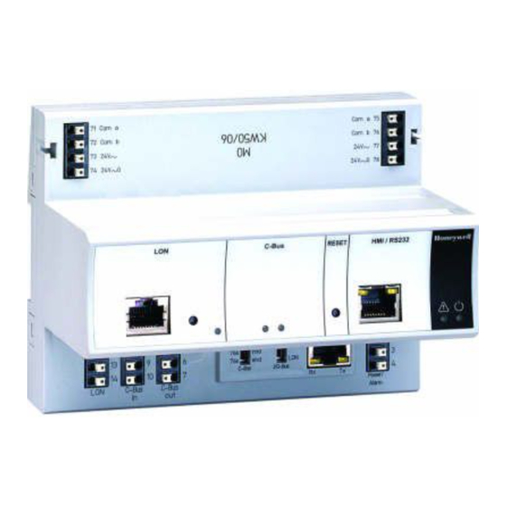
Page 7: Description Of The Xcl8010Au Controller Module
Excel 800 Description of the XCL8010AU Controller Module Description of the XCL8010AU Controller Module Overview PC or HMI EXCELON I/O MODULES NO CONNECTION LonWorks BUS C-BUS Fig. 3. Connections to the XCL8010AU Controller Legend Power supply for I/O modules I/O Bus communication terminals interface ORKS service button... - Page 8 LINE INPUT FUSE F1 (2 AMPS) PART NUMBERS ARE AS FOLLOWS: 2 AMP –HONEYWELL PART NO. 14000485-007 CONTROLLER (AVAILABLE FROM HONEYWELL BRANCH LOCATIONS, ONLY) POWER –BUSSMAN PART NO. AGC-2 –LITTLEFUSE PART NO. 312002 MAIN LINE VOLTAGE 120 VAC, 60 HZ...
-
Page 9: Earth Ground
Excel 800 Description of the XCL8010AU Controller Module CONTROLLER TRANSFORMER CONTROLLER SUPPLY 24 VAC ~ 71 48 VA 24 V 50 VA 14507351-001 429P156A E1A 1052 XXXX 120 V MAIN LINE (120 VAC, 60 Hz) TERMINAL “G” MUST BE CONNECTED TO A GOOD EARTH GROUND. -
Page 10: Interfaces And Bus Connections
Description of the XCL8010AU Controller Module Excel 800 Technical Data Corresponding Terminal Sockets Table 6. I/O modules and corresponding terminal sockets System Data I/O module socket scope of delivery Table 7. System data XF821AU, 1 terminal socket, XFL821AU 1 bridge connector Operating voltage 24 VAC/DC, 60 Hz 1 swivel label holder... -
Page 11: Data File Set-Up
Excel 800 Description of the XCL8010AU Controller Module CAUTION Locate separate from and below all building exhaust fans and upstream of any prevailing winds. Risk of electric equipment damage! Exhaust to outside of building. Failure to use listed/approved replacement parts can ►... -
Page 12: Xcl8010Au, I/O Modules On Single Rail
Description of the XCL8010AU Controller Module Excel 800 XCL8010AU, I/O Modules on Single Rail Connect XCL8010AU Controller Module and I/O modules ROOM 1 ► using the bridge connectors. This provides power supply and communication connection. LonWorks LonWorks No further wiring is necessary. XCL8010AU I/O MODULE I/O MODULE... -
Page 13: Setting Address Of Panel Bus I/O Modules
Excel 800 Description of the XCL8010AU Controller Module Panel Bus modules Panel Bus modules XCL8010AU LonWorks Bus modules Fig. 12. Mixed bus system – correct wiring Panel Bus modules LonWorks Bus modules XCL8010AU Fig. 13. Mixed bus system – incorrect wiring Setting Address of Panel Bus I/O Modules Use the rotary HEX switch to set the address to the one ►... -
Page 14: Setting The I/O Bus Switch
Mounting/Dismounting Modules Excel 800 Bus Topologies ORKS The L Bus is a 78-kilobit serial link that uses ORKS transformer isolation so that the bus wiring does not have a LOCK polarity. I.e. it is not important which of the two L ORKS Bus terminals are connected to each wire of the twisted pair. -
Page 15: Mounting/Dismounting Controller/Sockets
Excel 800 Mounting/Dismounting Modules Mounting/Dismounting Controller/Sockets Mounting Sockets NOTE: When using both Panel Bus and L ORKS I/O modules in an Excel 800 System, group both Panel Bus modules (light-gray) and L ORKS Bus I/O modules (dark-gray), e.g., on different rails. -
Page 16: Dismounting Sockets
Mounting/Dismounting Modules Excel 800 Fig. 21. Releasing latch Fig. 19. Connecting terminal sockets with bridge Mounting/Dismounting Electronic Modules connector NOTE: Bridge connectors transmit both communication Mounting Electronic Modules signals and power supply between modules. NOTE: Electronic modules can be removed from the Removing bridge connectors will interrupt the socket or inserted into the sockets without transmission of both communication signals and... -
Page 17: Dismounting Electronic Modules
Excel 800 Mounting/Dismounting Modules Setting the C-Bus Termination Switch Set the C-Bus termination switch S1 appropriately. ► Fig. 23. Locking the electronic module Fig. 25. C-Bus termination switch S1 NOTE: The red locking mechanism will not close if the electronic module is not properly mounted. Table 11. -
Page 18: Connecting Laptops (Xl-Online/Care)
Mounting/Dismounting Modules Excel 800 Connecting Laptops (XL-Online/CARE) Features Connect a laptop (on which e.g., XL-Online or CARE has ► been installed) to the HMI interface or L interface Interface and Terminals ORKS ORKS of the XCL8010AU Controller Module by means of The XCL8010AU Controller Module features –... -
Page 19: C-Bus Tx Led And Rx Led
Excel 800 Mounting/Dismounting Modules C-Bus Tx LED and Rx LED HMI Interface The XCL8010AU Controller Module is equipped with a Tx The XCL8010AU Controller Module is equipped with an HMI LED (status: yellow/OFF) and an Rx LED (status: Interface for the connection of HMIs, e.g., XI582 Operator yellow/OFF). -
Page 20: Alarm And Power Leds
Mounting/Dismounting Modules Excel 800 Alarm and Power LEDs Watchdog Status The XCL8010AU Controller Module is equipped with an alarm Table 19. Watchdog status (terminal 4) LED and a power LED. status signal on terminal 4 Failure (= alarm) 24 V Normal operation Modem Interface NO CONNECTION. -
Page 21: C-Bus Termination Switch S1
Excel 800 Description of the I/O Modules C-Bus Termination Switch S1 Description of the I/O Modules The XCL8010AU Controller Module features a 3-position C- Common Features Bus termination switch S1. This switch must be set in accordance with the given C-Bus Switches Located on the Terminal Socket configuration. -
Page 22: Analog Input Modules
Description of the I/O Modules Excel 800 Analog Input Modules Terminals Types of Analog Input Modules Table 25. Excel 800 Analog Input Modules type description housing XF821 Panel Bus Analog Input Module light-gray Bus Analog Input XFL821 dark-gray ORKS Module XS821-822 terminal socket light-gray... -
Page 23: Xfl821Au Connection Examples
Excel 800 Description of the I/O Modules XFL821AU Connection Examples 400 OHM SHIELD SHIELD 0(4) to 20 mA 0 to 10 V 0(4) to 20 mA (VIA EXTERNAL 0 TO 10 VDC 500 OHM RESISTOR). SHIELD SHIELD Pt1000 NTC20kW Fig. 37. XFL821AU Analog Input Module EN1B-0410GE51 R0908A... -
Page 24: Analog Output Modules
Description of the I/O Modules Excel 800 Analog Output Modules Terminals Types of Analog Output Modules Table 27. Excel 800 Analog Output Modules type description housing XF822 Panel Bus Analog Output light-gray Module XFR822 Panel Bus Analog Output light-gray Module with manual overrides Bus Analog Output XFL822 dark-gray... -
Page 25: Modules With Manual Overrides
Excel 800 Description of the I/O Modules Modules with Manual Overrides This updating (synchronization) is performed: • If the calculated position of the actuator The XFR822AU/XFLR822AU Analog Output Modules are < lower synchronization threshold (2 %) equipped with manual overrides: one rotary knob for each = synchronization towards 0 % analog output. -
Page 26: Binary Input Modules
Description of the I/O Modules Excel 800 Binary Input Modules Terminals Types of Binary Input Modules Table 30. Excel 800 Binary Input Modules type description housing XF823 Panel Bus Binary Input Module light-gray BI10 BI11 BI12 Bus Binary Input XFL823 dark-gray ORKS Module... -
Page 27: Status Leds
Excel 800 Description of the I/O Modules Status LEDs The status LEDs can be configured individually for use as either alarm LEDs (red/green) or as status LEDs (yellow/OFF [default]). Given a state of "logical ON," the LED will be lit (yellow or red). -
Page 28: Relay Output Modules
Description of the I/O Modules Excel 800 Relay Output Modules Terminals Types of Relay Output Modules Table 33. Excel 800 Relay Output Modules type description housing Relay block 1 Relay block 2 XF824 Panel Bus Relay Output Module light-gray Panel Bus Relay Output Module XFR824 light-gray with manual overrides... -
Page 29: Permissible Loads
Status LEDs with Manual Overrides Relay 3 N.O. contact REL3 N.O. Relay 3 N.C. contact REL3 N.C. Honeywell Relay 3 common contact R3 COM For connection of relay 3 common via R3 COM cross connector* Relay 4 N.O. contact REL4 N.O. -
Page 30: Connection Examples
Description of the I/O Modules Excel 800 Connection Examples 14507287 SERIES POWER MODULE Fig. 47. XF824AU connection example 14507287 SERIES POWER MODULE Fig. 48. XFR825AU connection example EN1B-0410GE51 R0908A... -
Page 31: Troubleshooting
Excel 800 Troubleshooting Troubleshooting Testing Wiring Connections The push-in terminals feature small holes (1 mm in diameter) which can be used to measure the signals. Insert a probe (1) as shown on the right. ► Fig. 49. Testing wiring connections Troubleshooting on the XCL8010AU Controller The following LEDs of the XCL8010AU Controller can be used for troubleshooting purposes: •... -
Page 32: Alarm Led (Red)
Excel 800 Alarm LED (red) Table 38. XCL8010AU alarm LED case alarm LED meaning remedy Normal operation No action necessary Watchdog alarm output is powered Try powering down and then ► – The controller has encountered a powering up the XCL8010AU. hardware problem If problem persists, check and –... -
Page 33: C-Bus Tx And Rx Leds
Excel 800 Troubleshooting Table 39. XCL8010AU L service LED ORKS case When can it occur? meaning remedy Node is configured and running normally Anytime No action necessary Bad node hardware Power up of controller Replace hardware ► Bad node hardware Power up of controller Replace hardware ►... -
Page 34: I/O Modules Troubleshooting
Excel 800 I/O Modules Troubleshooting Check if the power supply voltage level is OK and that there is no high voltage (> 24 VAC or > 40 VDC) connected to the ► inputs/outputs of the XF821AU, XFL821AU, XF822AU, XFL822AU, XFR822AU, XFLR822AU, XF823AU, and XFL823AU I/O modules. -
Page 35: Service Led Of I/O Modules
Excel 800 Troubleshooting Service LED of I/O Modules Table 43. Service LED of I/O modules case Service LED meaning remedy If the power LED is also OFF, then ► Replace hardware LED remains OFF after power-up – Defective device hardware –... - Page 36 Excel 800 Manufactured for and on behalf of the Environmental and Combustion Controls Division of Honeywell Technologies Sàrl, Rolle, Z.A. La Pièce 16, Switzerland by its Authorized Representative: Automation and Control Solutions Honeywell GmbH Böblinger Strasse 17 71101 Schönaich / Germany...
Need help?
Do you have a question about the XL 800 Series and is the answer not in the manual?
Questions and answers