Table of Contents
Advertisement
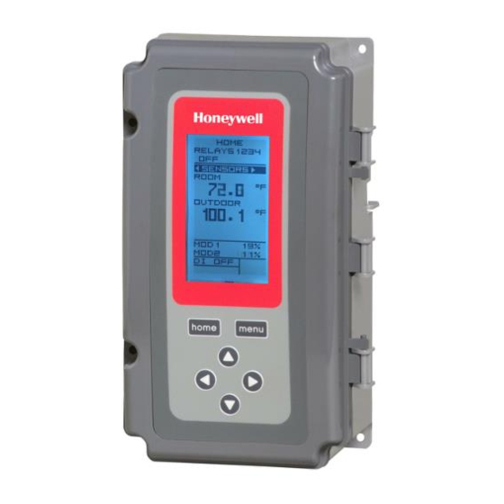
T775A/B/M Series 2000
Electronic Stand-Alone
Controllers
Controller
a
Model
Description
T775A2009 Standard
T775B2016 Standard
T775B2024 Standard
T775B2032 Standard
T775B2040 Standard
T775M2006 Modulating
T775M2014 Modulating
T775M2022 Modulating
T775M2030 Modulating
T775M2048 Modulating
a
All models include a digital input for use with the disable or setback option.
b
The modulating (analog) outputs are 4-20 mA, 0-10 Vdc, 2-10 Vdc, or Series 90 selectable.
c
Each floating output eliminates two SPDT relays.
d
These models can support a high/low modulating limit at Sensor B for temperature control at Sensor A.
Table 1. T775A/B/M Controller Configurations.
Replaces
T775A1001
N/A
T775C1009 T775D1008 4
T775A1019 T775B1000 2
T775A1027 T775A1035
T775B1018 T775B1026
T775B1042
N/A
T775G1005 T775G1013
T775G1021 T775G1039
N/A
T775E1114 T775F1022
T775F1055 T775F1089
T775E1015 T775E1023
T775E1056 T775E1064
T775E1098
INSTALLATION INSTRUCTIONS
PRODUCT DESCRIPTION
The T775 electronic stand-alone controllers are the next
generation of commercial and agricultural controls
capable of remote sensing of temperature and providing
switched and/or proportional outputs to various types of
loads.
Five models have analog (modulating) outputs for
Actuator and motor control, and NEMA-4 weatherproof
enclosures are available for wet environments.
IMPORTANT
Each T775A/B/M controller is an operating
control, not a limit or safety control. If used in
applications requiring safety or limit controls, a
separate safety or limit control device is
required.
Analog
SPDT
(Mod)
Floating
Relay
b
Outputs
Outputs
Outputs
1
None
None
2
None
1
None
2
None
1
4
None
2
None
2
N/A
4
2
N/A
2
2
N/A
4
2
N/A
2
2
N/A
Nbr of
Sensors
c
Inputs
Included Enclosure
1
1
NEMA 1
2
1
NEMA 4X
2
1
NEMA 4X
2
1
NEMA 1
2
1
NEMA 1
2
1
NEMA 1
1
NEMA 4X
d
2
1
NEMA 4X
d
2
1
NEMA 1
d
2
1
NEMA 1
d
2
62-0254-13
Advertisement
Table of Contents

Related Manuals for Honeywell T775A/B/M 2000 Series


Summary of Contents for Honeywell T775A/B/M 2000 Series
- Page 1 T775A/B/M Series 2000 Electronic Stand-Alone Controllers INSTALLATION INSTRUCTIONS PRODUCT DESCRIPTION The T775 electronic stand-alone controllers are the next generation of commercial and agricultural controls capable of remote sensing of temperature and providing switched and/or proportional outputs to various types of loads.
- Page 2 T775A/B/M SERIES 2000 ELECTRONIC STAND-ALONE CONTROLLERS Temperature Sensors Accessories The controller accepts 1,097 Ohms PTC at 77°F (25°C): • 107324A – Bulb Holder, duct insertion • 50021579-001 – Standard sensor (included with all • 107408 – Heat Conductive Compound, 4 ounce models except NEMA 4X models) •...
- Page 3 T775A/B/M SERIES 2000 ELECTRONIC STAND-ALONE CONTROLLERS BEFORE INSTALLATION The controller may be mounted in any orientation. However, mounting in the orientation shown in Fig. 1 on page 2 permits proper viewing of the LCD display and use Review the “SPECIFICATIONS” on page 35 before of the keypad.
- Page 4 T775A/B/M SERIES 2000 ELECTRONIC STAND-ALONE CONTROLLERS Wiring Connections Access Multiple Parallel Sensors Multiple sensors can be parallel-series wired to sense To access the wiring connections, remove the two screws average temperatures in large spaces. To maintain control on the left side of the enclosure and gently swing open the accuracy, the number of sensors to be parallel-series top.
- Page 5 T775A/B/M SERIES 2000 ELECTRONIC STAND-ALONE CONTROLLERS Controller Wiring See Fig. 7 on page 6 for locating the appropriate power input, remote sensors input, low voltage, contact closure, and load output terminals. WARNING Access to the terminals can be gained through standard conduit knockouts (A through E in Fig.
- Page 6 T775A/B/M SERIES 2000 ELECTRONIC STAND-ALONE CONTROLLERS Controller Wiring Details Table 2. Description of Wiring Terminal Connections. (Continued) The wiring connection terminals are shown in Fig. 7 and Connection Terminal Label Description are described in Table 2. Input See Fig. 8 – 22 beginning on page 6 for typical T775A/B/ Digital Input (dry M wiring applications.
- Page 7 T775A/B/M SERIES 2000 ELECTRONIC STAND-ALONE CONTROLLERS SENSOR A SENSOR A (HOT) 24 VAC 240V LOAD L1 (HOT) POWER SUPPLY LOAD LOAD 2 LOAD LOAD 1 M33847 LOAD M24476A Fig. 11. Wiring for Two-Stage Control with 240 Vac. Fig. 9. Wiring for Four-Stage Control – 24 Vac Input and 24 Vac Load.
- Page 8 DIGITAL LOAD 4 INPUT M33849 M24482 Fig. 13. Wiring for Four-Stage Control with 240 Vac. Fig. 16. Wiring for Digital Input (Dry Contact). HONEYWELL MODUTROL MOTOR WITH 4-20 mA MODULATING INPUT – + T1 T2 120/240 VAC LINE POWER DEVICE...
- Page 9 T775A/B/M SERIES 2000 ELECTRONIC STAND-ALONE CONTROLLERS HONEYWELL MODUTROL MOTOR WITH HONEYWELL MINIMUM POSITION VOLTAGE CONTROL INPUT SPDT CHANGEOVER ELECTRONIC SERIES 90 POTENTIOMETER (H205 OR H705) MODUTROL MOTOR (Q209) T1 T2 W R B T1 T2 B POWER POWER – –...
- Page 10 T775A/B/M SERIES 2000 ELECTRONIC STAND-ALONE CONTROLLERS M9184 OR M9185 (HOT) MODUTROL MOTOR – M9184 OR M9185 MODUTROL MOTOR – M9184 OR M9185 MODUTROL MOTOR MODULATING OUTPUT TERMINAL (MOD 1) POWER SUPPLY. PROVIDE DISCONNECT MEANS AND OVERLOAD PROTECTION AS REQUIRED. USE A 1300 OHM RESISTOR FOR TWO MOTORS, 910 OHM RESISTOR FOR THREE MOTORS. THE 407EAU RESISTOR KIT, WHICH IS SHIPPED WITH THE M9184 AND M9185 MOTORS, INCLUDES BOTH RESISTORS.
- Page 11 T775A/B/M SERIES 2000 ELECTRONIC STAND-ALONE CONTROLLERS CHECKOUT Table 3. Temperature Sensor Calibration for Resis- tance Loss Due to Wire Length. Inspect all wiring connections at the controller terminals, Temperature Offset in and verify compliance with the installation wiring diagrams. °F (Foot) Rating mΩ/ft 200 ft...
- Page 12 T775A/B/M SERIES 2000 ELECTRONIC STAND-ALONE CONTROLLERS INTERFACE OVERVIEW Menu Button • Pressing the MENU button always displays the The T775A/B/M controllers use an LCD panel and Program menu. If you are in Setup mode, you exit 6-button keypad to provide status information and permit setup and return to the Program menu.
- Page 13 T775A/B/M SERIES 2000 ELECTRONIC STAND-ALONE CONTROLLERS Setup Menu IMPORTANT After four minutes of inactivity (no buttons To access the Setup menu, press and hold the MENU pressed), the LCD display reverts to the home button for five seconds (Refer to Fig. 27). screen display.
- Page 14 T775A/B/M SERIES 2000 ELECTRONIC STAND-ALONE CONTROLLERS 1.PROGRAMMING Cooling Mode Setpoint and Differential The controller must be programmed before being placed into service. In cooling mode, the differential is above the setpoint. The relay de-energizes when the temperature falls to the IMPORTANT setpoint.
- Page 15 T775A/B/M SERIES 2000 ELECTRONIC STAND-ALONE CONTROLLERS 1.2. Program Menu for Outputs MENU PROGRAM PROGRAM Press the MENU button, select PROGRAM, then select RELAY 1 RELAY 1 RELAY 1 (or MOD 1) to view the parameters. Fig. 29 SETPOINT shows RELAY 1. DIFFRNTL SENSOR NOTE: For MOD 1 and 2, THROT RNG replaces...
- Page 16 T775A/B/M SERIES 2000 ELECTRONIC STAND-ALONE CONTROLLERS 1.2.3. SENSOR MENU PROGRAM PROGRAM RELAY 1 RELAY 1 SENSOR SENSOR 1. From the menu, use the buttons to SENSOR A highlight SENSOR. SENSOR B 2. Press the button to display the sensor selec- tions.
- Page 17 T775A/B/M SERIES 2000 ELECTRONIC STAND-ALONE CONTROLLERS 1.2.7. Exiting Program Mode MENU Press the HOME button to leave programming mode and PROGRAM return to the home screen. MOD 1 MOD 2 This completes the programming procedure. RELAY 1 RELAY 2 RELAY 3 RELAY 4 EXIT M24499...
- Page 18 T775A/B/M SERIES 2000 ELECTRONIC STAND-ALONE CONTROLLERS 2.2.1. Number of SENSORS SETUP SETUP SENSORS SENSORS # SENSORS # SENSORS The value entered here determines the number of sensors displayed on the home screen. 1. From the Sensors menu, highlight # SENSORS then press the button to display the number of sensors.
- Page 19 T775A/B/M SERIES 2000 ELECTRONIC STAND-ALONE CONTROLLERS SETUP 2.2.2.3. LABEL SETUP (the sensor input) SENSORS SENSORS SENSOR A SENSOR A For a sensor already labeled, the display positions to and LABEL LABEL highlights that label. SENSOR A 1. From the Sensor A selections, use the BOILER A OUTDOOR A buttons to highlight LABEL.
- Page 20 T775A/B/M SERIES 2000 ELECTRONIC STAND-ALONE CONTROLLERS SETUP 2.2.4. LIMIT SETUP (Sensor B only) SENSORS SENSORS SENSOR B SENSOR B For the T775M2030 and T775M2048 models only, the LIMIT LIMIT LIMIT item displays on the Sensor B menu. DISABLE HI LIMIT NOTE: The LIMIT option acts only on Modulating LOW LIMIT Output 1.
- Page 21 T775A/B/M SERIES 2000 ELECTRONIC STAND-ALONE CONTROLLERS 2.2.4.2. THROTTLING RANGE (Sensor B SETUP SETUP SENSORS SENSORS only) SENSOR B SENSOR B The throttling range for the modulating high or low limit UNITS positions the setpoint at the end of the throttling range. CALIBRATE SETUP LABEL...
- Page 22 T775A/B/M SERIES 2000 ELECTRONIC STAND-ALONE CONTROLLERS SETUP 2.3.1.1. TYPE SETUP (of output signal) OUTPUTS OUTPUTS MOD 1 MOD 1 TYPE TYPE 1. From the Mod menu, use the buttons 4 - 20 mA to highlight TYPE. 0-10 V 2. Press the button to display the Type selections.
- Page 23 T775A/B/M SERIES 2000 ELECTRONIC STAND-ALONE CONTROLLERS SETUP 2.3.1.4. DERIVATIVE SETUP OUTPUTS OUTPUTS MOD 1 MOD 1 The Derivative default value is factory set to zero (no DERIVATIV DERIVATIV derivative control). It is strongly recommended that the derivative remain at zero (0) unless you have a very good reason to adjust it.
- Page 24 T775A/B/M SERIES 2000 ELECTRONIC STAND-ALONE CONTROLLERS 2.3.1.7. EXIT SETUP OUTPUTS Press the button (or highlight EXIT and press the MOD 1 button) to exit the Mod menu and return to the Outputs TYPE menu. MIN OUT % INTEGRAL If you have a second modulating output to configure, go to DERIVATIV SCHEDULE “2.3.1.
- Page 25 T775A/B/M SERIES 2000 ELECTRONIC STAND-ALONE CONTROLLERS SETUP 2.3.3.1. USE SCHED SETUP OUTPUTS OUTPUTS OPTIONS OPTIONS USE SCHED USE SCHED 1. Press the button to display the schedule selections. 2. Use the buttons to highlight YES or NO. Default: NO 3. Press the button to accept the value and display the MIN OFF option.
- Page 26 T775A/B/M SERIES 2000 ELECTRONIC STAND-ALONE CONTROLLERS SETUP 2.3.3.3. DI OPTIONS SETUP (digital input options) OUTPUTS OUTPUTS OPTIONS OPTIONS The DI Option you select applies to all outputs. This DI OPTS DI OPTS option overrides any Setpoint/Setback values entered in DISABLE the Schedule.
- Page 27 T775A/B/M SERIES 2000 ELECTRONIC STAND-ALONE CONTROLLERS 2.3.3.6. Exit Options Setup SETUP OUTPUTS OPTIONS Press the button (or highlight EXIT and press the USE SCHED button) to exit and return to the Outputs menu. MIN OFF DI OPTION Continue with “2.3.4. Setting up the Relays” SHOW RT EXIT M24525...
- Page 28 T775A/B/M SERIES 2000 ELECTRONIC STAND-ALONE CONTROLLERS 2.3.4.1.1. Floating Relay Menu SETUP SETUP OUTPUTS OUTPUTS The Floating option is only available on the T775B2016, FLOAT 1 FLOAT 1 T775B2024, T775B2032, and T775B2040 models. TYPE ACTUATOR When Relay 1 or Relay 3 is setup as floating, relays are INTEGRAL paired and the Float 1 or Float 2 menu displays with the DERIVATIV...
- Page 29 T775A/B/M SERIES 2000 ELECTRONIC STAND-ALONE CONTROLLERS SETUP 2.3.4.1.1.3. DERIVATIVE SETUP (modulating/floating OUTPUTS OUTPUTS FLOAT 1 FLOAT 1 relay only) DERIVATIV DERIVATIV The Derivative option displays only on the T775B2016, T775B2024, T775B2032, and T775B2040 models when the Type option = Floating. 1.
- Page 30 T775A/B/M SERIES 2000 ELECTRONIC STAND-ALONE CONTROLLERS 2.4. EXIT Setup Mode SETUP OUTPUTS Press the button to exit the selected relay set up and RELAY 1 return to the Outputs menu. RESET SCHEDULE To setup the next relay output go to “2.3.4. Setting up the RESET RT Relays”...
- Page 31 T775A/B/M SERIES 2000 ELECTRONIC STAND-ALONE CONTROLLERS 3.2. OPTIONS MENU MENU SCHEDULE SCHEDULE 1. From the Schedule menu, use the but- OPTIONS OPTIONS tons to highlight OPTIONS. SET TIME 2. Press the button to display the Options menu. SET DATE DAYLIGHT EXIT M24537 Fig.
- Page 32 T775A/B/M SERIES 2000 ELECTRONIC STAND-ALONE CONTROLLERS MAIN 3.2.3. DAYLIGHT MAIN (daylight saving time) SCHEDULE SCHEDULE OPTIONS OPTIONS DAYLIGHT DAYLIGHT 1. From the Options menu, use the but- tons to highlight DAYLIGHT. 2. Press the button to display the current system setting for daylight saving time.
- Page 33 T775A/B/M SERIES 2000 ELECTRONIC STAND-ALONE CONTROLLERS MAIN 3.3.1. E1 SETPT MENU (setpoint for event 1) SCHEDULE SCHEDULE MON-FRI MON-FRI E1 SETPT E1 SETPT 1. From the selected time period menu, use the buttons to highlight E1 SETPT. SETPOINT SETBACK 2. Press the button to display the setpoint options.
- Page 34 T775A/B/M SERIES 2000 ELECTRONIC STAND-ALONE CONTROLLERS SUMMARY MENU TROUBLESHOOTING The Summary menu provides the ability to view the Power Loss schedule (E1 and E2 times) for each relay for each day of the week. The date and time settings are retained for 24 hours after a power outage.
- Page 35 T775A/B/M SERIES 2000 ELECTRONIC STAND-ALONE CONTROLLERS SPECIFICATIONS Safety Compliance UL 60730-1 for US and Canada Power: 24, 120, or 240 Vac; 50/60 Hz; A separate earth ground is required for any power source. FCC Compliance Statement: Power Consumption: This equipment has been tested and found to comply with •...
- Page 36 T775A/B/M SERIES 2000 ELECTRONIC STAND-ALONE CONTROLLERS By using this Honeywell literature, you agree that Honeywell will have no liability for any damages arising out of your use or modification to, the literature. You will defend and indemnify Honeywell, its affiliates and subsidiaries, from and against any liability, cost, or damages, including attorneys’...
Need help?
Do you have a question about the T775A/B/M 2000 Series and is the answer not in the manual?
Questions and answers