
Related Manuals for Zibro PX 643


Summary of Contents for Zibro PX 643
- Page 1 PX 643 BEDIENUNGSANLEITUNG BRUGSANVISNING INSTRUCCIONES DE USO MANUEL D'UTILISATION OPERATING MANUAL ISTRUZIONI D’USO > GEBRUIKSAANWIJZING INSTRUKCJA OBSŁUGI...
-
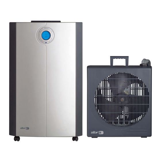
Page 2: Important Components
IMPORTANT COMPONENTS Control Panel Air outlet Carrying handle Caster wheels Water container Air filter Air inlet Exhaust air outlet Cord storage Water stopper / drainage point Connection tube Cabinet cover for quick connector shielding Bracket Spanners Remote control Screws (8x) Protection caps for connector (2x) - Page 3 Dear Sir, Madam, Congratulations on the purchase of your air conditioner. In addition to air cooling, this air conditioner has three other functions: air dehumidification, air circulation and air filtration. The mobile air conditioner is easy to operate and move. You have acquired a high quality product that will provide you with many years of pleasure, on condition that you use it responsibly.
-
Page 4: A Safety Instructions
SAFETY INSTRUCTIONS Install the device only when it complies with local regulations, by-laws and standards. The unit is only suitable for use in dry locations, indoors. Check the mains voltage and frequency. This unit is only suitable for earthed sockets, connection voltage 220-240 V. -
Page 5: Installation Of The Indoor Unit
ATTENTION! • Never use the device with a damaged power cord, plug, cabinet or control panel. Never trap the power cord or allow it to come into contact with sharp edges. • Failing to follow the instructions may lead to nullification of the guarantee on this device. -
Page 6: Installation Of The Outdoor Unit
INSTALLATION OF THE OUTDOOR UNIT The outdoor unit can be placed on the floor (of a balcony) or hung on a wall. The location for the outdoor unit has to be well ventilated (to exhaust heat) and reachable from the indoor; such as under a window, on a veranda or in a corridor. The outdoor unit does not necessarily have to be mounted to the bracket. -
Page 7: Operation
OPERATION 1. CONNECTING TO THE MAIN Insert the plug in the wall socket. Then press to switch the unit on or off. A buzzer will beep, and the LCD will display 12:00 o’clock as default. 2. SETTING THE CLOCK 88: : 8 8 8 8 Press the push button for 3 seconds to set the clock. -
Page 8: Timer Setting
6. TIMER SETTING The timer can be set in the following configurations: Programming the timer for ON - when the unit is OFF. 88: : 8 8 8 8 Press the push button; the 2 left digits of the 4 digits on the LCD display are flashing. - Page 9 Repeat OFF & ON Programming the timer for repeat OFF & ON - when the unit is running. 88: : 8 8 8 8 Press the push button; the 2 left digits of the 4 digits on the LCD display are flashing.
-
Page 10: Air Filter
7. CANCELLING THE TIMER FUNCTION In order to cancel the timer programming press the push button momentarily, then it will return to the time display. The daily mode will be cancelled as well. The black segments in the circular time scale will disappear. 8. - Page 11 The filter frame on the backside of the unit can be opened. The active carbon filter and 3M™ Filtrete™ filter can be installed or removed. The screen filter is part of the filter frame (see illustration). The screen filter has to be cleaned regularly with a vacuum cleaner to avoid blocking of the air flow.
-
Page 12: Remote Control
EMPTY INTERNAL WATER CONTAINER When the water flow to the outdoor unit is blocked, or the position of the outdoor unit is too high, water may accumulate in the internal water container of the unit. When the internal water container is full the backlight on the LCD- display will be flashing. - Page 13 (DIS)CONNECTING THE INDOOR AND OUTDOOR UNIT (FOR QUALIFIED PERSONNEL) DISCONNECTING Switch off the unit, remove the plug from the mains and leave it idle for at least 30 minutes. Open the cabinet cover for quick connector shielding Disconnect the electric cable (A). Disconnect the drain tube (C).
- Page 14 Close the cabinet cover for quick connector shielding Store the protection caps in a safe place. WARNING After connecting the refrigerant tubes, take care that these are well isolated again. If this is not done properly, damage because of condensation water can occur! IMPORTANT Always ensure that the quick-connection openings are clean.
-
Page 15: Jtrouble Shooting
NOTE! Do not store the units disconnected, to prevent leakage of refrigerant. TROUBLE SHOOTING Problem Cause Solution Connect to a functioning outlet No power supply. and switch on. The unit does Empty the internal water Is the LCD light flashing. not function. -
Page 16: Guarantee Conditions
GUARANTEE CONDITIONS The air conditioner is supplied with a 24-month guarantee, commencing on the date of purchase. All material and manufacturing defects will be repaired or replaced free of charge within this period. The following rules apply: We expressly refuse all further damage claims, including claims for collateral damage. -
Page 17: Ltechnical Data
TECHNICAL DATA Model PX 643 Cooling capacity * EE Class * EER * Power consumption Current (nom.) Power supply V/Hz/PH 220 – 240 / 50 / 1 Air flow (nom.) (indoor unit) Dehumidifying capacity ** L/24h For rooms up to... - Page 18 3350 HAAG Holloway Bank, Wednesbury tel: +43 7434/44867 West Midlands WS10 OAW fax: +43 7434/44868 Tel.: +44 121 506 1818 email: pvgaustria@zibro.com Fax: +44 121 505 1744 email: gases@lister.co.uk e BELGIË PVG Belgium NV/SA > ITALIA Industrielaan 55 PVG Italy SRL 2900 SCHOTEN Via Niccolò...
Need help?
Do you have a question about the PX 643 and is the answer not in the manual?
Questions and answers