ACV HeatMaster HM 200 N Technical Specification
Hide thumbs
Also See for HeatMaster HM 200 N:
- Specification (2 pages) ,
- Product catalogue (27 pages) ,
- Product manual (49 pages)
Table of Contents
Advertisement
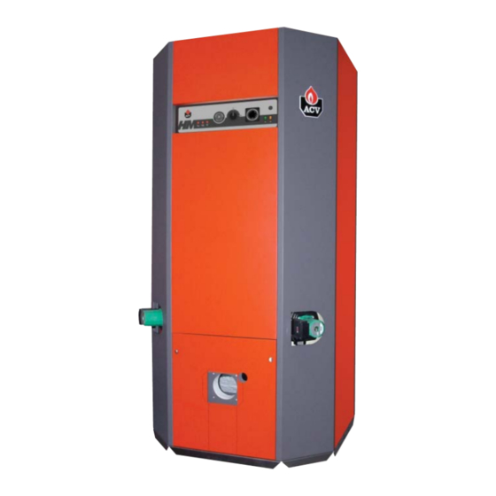
EFFECTIVE DIMENSIONS
The appliances delivered are factory-tested. Upon receipt, remove the packing and check that there is no damage to the appliances. Refer to the
dimensions and weights listed below for transport purposes.
The jacket is fitted by the installer on site
A
B
HeatMaster
®
200 N
HeatMaster
®
200 F
GENERAL CHARACTERISTICS
Fuel
Input
Output
Maintenance loss of nominal value at 60°C
Total capacitye
Primary circuit capacity
Hot water connection
Heating connection
Chimney connection
Water tank heat transfer surface
Drained weight
Pressure loss of the primary circuit
Combustion efficiency
Output CO
2
Net temperature of the flue gases
Mass flow rate of combustion products
Nozzle (Fuel oil)
Pump pressure (Fuel oil)
(*) The HeatMaster
®
200F outputs can only be reached if the boiler is fitted with a "RIELLO" RG4S 396 T1 fuel oil burner.
(see the assembly instructions in the wooden protective casing)
G
D
H
A mm
B mm
C mm
2085
-
1020
2085
190
1020
TECHNICAL SPECIFICATION
F
E
D mm
E mm
-
1020
1210
1020
HM 200 N
type
Fuel / Gas
kW
154.0
kW
141.7
%
0.43
L
641
L
241
Ø
2"
Ø
2"
Ø mm
250
m
2
5.30
Kg
530
mbar
240
%
93.5
%
12.8
°C
143
g/sec.
65.2
gal/h
3.25 / 60° B
bar
11.0
.
302
506
C
250
F mm
G mm
600
1383
600
1383
HM 200 F
Fuel
196.0
180.3
0.34
641
241
2"
2"
250
5.30
550
240
93.7
12.9
140.5
83.0
4.00 / 60° B
11.6
338
250
190
H mm
590
590
5
Advertisement
Table of Contents

Related Manuals for ACV HeatMaster HM 200 N


Summary of Contents for ACV HeatMaster HM 200 N
- Page 1 TECHNICAL SPECIFICATION EFFECTIVE DIMENSIONS The appliances delivered are factory-tested. Upon receipt, remove the packing and check that there is no damage to the appliances. Refer to the dimensions and weights listed below for transport purposes. The jacket is fitted by the installer on site (see the assembly instructions in the wooden protective casing) A mm B mm...
-
Page 2: Technical Specification
TECHNICAL SPECIFICATION DOMESTIC HOT WATER PERFORMANCES HM 200 N HM 200 F Peak delivery at 40°C L/10’ 1570 1675 Peak delivery at 45°C L/10’ 1350 1444 Peak delivery at 60°C L/10’ Peak delivery at 70°C L/10’ Peak delivery at 80°C L/10’... -
Page 3: Installation
INSTALLATION BOILER ROOM Note: Regulations vary from country to country therefore Important the table above is intended only as a guide. • Keep vents free at all times. • Do not store inflammable products in the boiler room. • Do not store corrosive products near the boiler, such as paints, solvents, chlorine, salt, soap and other cleaning products. -
Page 4: Hot Water Connections
If the mains water pressure is greater than 6 bar, a pressure reducing valve must be fitted. Expansion relief valve The tank expansion relief valve must be ACV approved and calibrated to a maximum of 7 bar. The valve discharge must be connected to the drain. -
Page 5: Heating Connection
INSTALLATION HEATING CONNECTION FUEL OIL SUPPLY CONNECTION The HeatMaster ® has two connections at the rear that can be used (If another make of buner is fitted please refer to that manufacturers technical to connect a central heating circuit. Connecting a heating system manual.) may reduce the domestic hot water performance. -
Page 6: Electrical Connections
INSTALLATION ELECTRICAL CONNECTIONS WIRING DIAGRAM Electrical supply HeatMaster ® wiring diagram legend 200 N / 200 F The boiler operates with a 230 V - 50 Hz single phase supply. A double pole isolator with a 6 amp fuse or a 6 amp circuit breaker 230 V power connection plug switch to cut the power supply when servicing or repairing the boiler. -
Page 7: Maintenance
In the event of heavy use of the boiler, it may require servicing on a Hot water tank must be pressurised before the more regular basis than once a year. In this case, contact ACV for heating circuit is filled. -
Page 8: Draining The Boiler
MAINTENANCE MISE EN SÉCURITÉ DRAINING THE BOILER PLACING THE BURNER IN SAFETY MODE Water flowing out of the drain cock may be When the burner is in safety mode, the safety indicator located on D A N G E R extremely hot and could cause severe scalding.
Need help?
Do you have a question about the HeatMaster HM 200 N and is the answer not in the manual?
Questions and answers