Advertisement
273 Branchport Avenue
Long Branch, N.J. 07740
(800) 631-2148
www.wheelockinc. com
Use this product according to this instruction manual. Please keep this instruction manual for future reference.
MODELS: ST-H15-B & ST-H30
GENERAL:
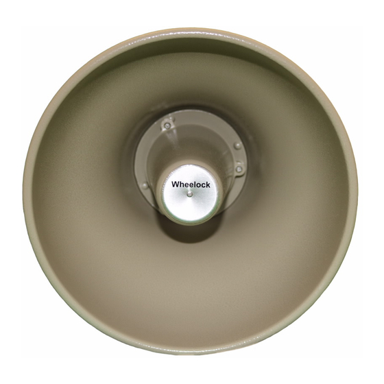
Horn speakers should be used in large and/or noisy locations. They are weatherproof and may be used indoors or outdoors. The
setting of the variable transformer tap selector switch should be set to provide a sound output of at least 6dB for paging, and 3dB for
background music above the background noise everywhere in the paging zone. However, the horn speaker's volume should not be set
so high as to cause discomfort to those closest to the horn. In some cases, use of multiple horns set at lower volume provide better
sound coverage, than one horn set at full volume. Horns should be mounted at least 15 feet above the floor, and angled downward.
NOTE: All CAUTIONS and WARNINGS are identified by the symbol
WARNING:
READ THESE INSTRUCTIONS CAREFULLY.
FOLLOWING INSTRUCTIONS, CAUTIONS AND WARNINGS COULD RESULT IN IMPROPER APPLICATION,
INSTALLATION AND/OR OPERATION OF THESE PRODUCTS IN AN EMERGENCY SITUATION, WHICH COULD
RESULT IN PROPERTY DAMAGE, SERIOUS INJURY OR DEATH TO YOU AND/OR OTHERS.
SPECIFICATIONS:
Wattage Selector Switch Settings:
Setting
100V
1
2.0W
2
4.0W
3
7.5W
4
15.0W
5
Not Used
6
Not Used
7
Not Used
1) Power Handling Capacity (RMS): 15 Watts (ST-H15-B), 30 Watts (ST-H30) 2) Sound Dispersion: 110 Degrees 3) Constant
Voltage Line: 25V, 70V or 100V 4) Frequency Response: 375 - 10,000Hz (@ Full Rated Output) 5) Sound Level At Rated Output
(ST-H15-B): 122dB (SPL-On Axis, @ 1 Meter, @ Rated Power) 6) Sound Level At Rated Output (ST-H30): 125dB (SPL-On Axis,
@ 1 Meter, @ Rated Power)
7) Dimensions: 8-15/16"Dia. X 10"Dia.
CAUTION: Do not place switch in settings marked "not used". Failure to comply with these restrictions may cause damage to
components and will void the warranty.
Copyright 1993, 1994, 1995, 2000 Wheelock, Inc. All rights reserved.
Thank you for using our products.
INSTALLATION INSTRUCTIONS
HORN SPEAKER WITH MULTI-TAP TRANSFORMER
ST-H15-B
70V
1.0W
Not Used
2.0W
Not Used
3.8W
7.5W
15.0W
Not Used
Not Used
. All warnings are printed in bold capital letters.
FAILURE TO COMPLY WITH ANY OF THE
Table 1.
25V
Setting
1
2
0.48W
3
0.94W
4
1.8W
5
7.5W
6
15.0W
7
ST-H30
100V
70V
4.0W
2.0W
7.5W
3.8W
15.0W
7.5W
30.0W
15.0W
Not Used
30.0W
Not Used
Not Used
Not Used
Not Used
25V
0.3W
0.5W
0.9W
1.9W
3.8W
6.9W
13.9W
P82595 C
Sheet 1 of 5
Advertisement
Table of Contents

Summary of Contents for Wheelock ST-H15-B
- Page 1 Voltage Line: 25V, 70V or 100V 4) Frequency Response: 375 - 10,000Hz (@ Full Rated Output) 5) Sound Level At Rated Output (ST-H15-B): 122dB (SPL-On Axis, @ 1 Meter, @ Rated Power) 6) Sound Level At Rated Output (ST-H30): 125dB (SPL-On Axis, @ 1 Meter, @ Rated Power) 7) Dimensions: 8-15/16"Dia.
- Page 2 30 Ft. NOTES: 1. Mounting Height is 15-20 Feet. 2. Typical Mounting Angle (to Vertical) is 60 degrees. * For very noisy locations (above 96dB), consult Wheelock for applications assistance. ST-H15-B Distance from Horn (Ft. on Axis) ST-H30 Distance from Horn (Ft. on Axis) CAUTION: The total system wattage requirement should not exceed 85% of the system amplifiers rated output.
- Page 3 MOUNTING INFORMATION: The horn speakers may be wall mounted by simply using the holes in the swivel base to locate and drill mounting holes. Mount the base to the surface with appropriate hardware. Slots are also provided in the base for banding straps, to allow mounting to beams, poles, and girders.
- Page 4 WIRING INFORMATION: Remove the Interface Adaptor, or clear plastic shield to expose the two (2) screw terminals, and connect the audio installation wires as shown in Figure 3. The terminals are numbered (1 and 2) to indicate phasing, which should be maintained throughout the systems. For example: In an installation with multiple horns, connect the same color audio wire to all number 1 terminals and another color audio wire to all number 2 terminals to ensure proper phasing, as shown in Figure 4.
-
Page 5: Limited Warranty
DOCUMENTS DESCRIBING THE PRODUCT FOR USE IN PROMOTIONAL OR ADVERTISING CLAIMS, OR FOR ANY OTHER USE, INCLUDING DESCRIPTION OF THE PRODUCT'S APPLICATION, OPERATION, INSTALLATION AND TESTING IS USED AT THE SOLE RISK OF THE USER AND WHEELOCK WILL NOT HAVE ANY LIABILITY FOR SUCH USE.


Need help?
Do you have a question about the ST-H15-B and is the answer not in the manual?
Questions and answers