Advertisement
Quick Links
273 Branchport Avenue
Long Branch, NJ 07740
(800) 631-2148
www.wheelockinc.com
Use this product according to this instruction manual. Please keep this instruction manual for future reference.
GENERAL:
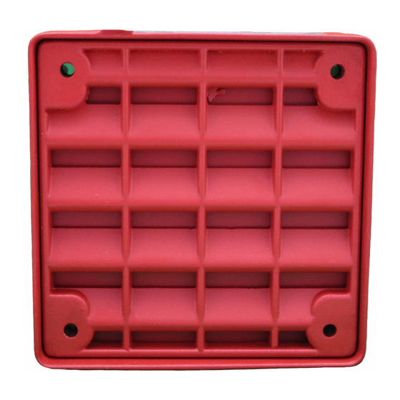
Wheelock's Series ET-1010 Low Profile Vandal Resistant Speaker is UL Standard 1480 for Speaker Appliances. The speaker is
designed for multiple power requirements with high dBA output at each power tap. All models offer a choice of field selectable
taps, 1/8W to 8W for either 25.0VRMS or 70.0VRMS audio systems. All models are UL Listed for indoor and outdoor wet with
the backboxes specified in these instructions (see Mounting Options).
NOTE: All CAUTIONS and WARNINGS are identified by the symbol
WARNING: PLEASE READ THESE INSTRUCTIONS CAREFULLY. FAILURE TO COMPLY WITH ANY OF
THE
FOLLOWING
APPLICATION, INSTALLATION AND/OR OPERATION OF THESE PRODUCTS IN AN EMERGENCY SITUATION,
WHICH COULD RESULT IN PROPERTY DAMAGE AND SERIOUS INJURY OR DEATH TO YOU AND/OR
OTHERS.
SPECIFICATIONS:
WIRING INFORMATION:
1. Field selectable input terminals are provided on each unit. The following wattage selections are available: 1/8W, 1/4W,
1/2W, 1W, 2W, 4W and 8W. Frequency range of speakers is 400-4000Hz.
2. A 10µF blocking capacitor for DC supervision of audio lines by the FACP is factory wired in series with the speaker input.
The maximum supervision voltage is 33 volts DC.
FROM PRECEDING SPEAKER
OR FIRE ALARM
CONTROL PANEL (FACP)
Copyright 2005 Wheelock, Inc. All rights reserved
Thank you for using our products.
INSTALLATION INSTRUCTIONS
ET-1010 VANDAL RESISTANT SPEAKER
INSTRUCTIONS,
CAUTIONS
Table 1: UL Listed Models and Ratings
Vandal
Speaker
Resistant
Voltage
Models
(VRMS)
ET-1010
25/70
NOTE
: dBA is rated per UL Standard 1480 for Speaker Appliances.
Figure 1:
TO NEXT SPEAKER
OR END OR LINE RESISTOR
(EOLR)
COM+
. All warnings are printed in bold capital letters.
AND
WARNINGS COULD RESULT
Speaker dBA at 10 Feet
(Rated Watts)
1/8
1/4
1/2
1
77
80
83
86
Figure 2:
IN
2
4
8
87
92
94
1. Low Profile ET Series Speaker models have
in-out wiring terminals that accept two #12 to
#18 American Wire Gauge (AWG) wires at
each screw terminal. Strip leads 3/8 inches
and connect to screw terminals.
2. Break all in-out wire runs on supervised
circuits
to
assure
integrity
supervision as shown in Figure 2. The polarity
shown in the wiring diagrams is for operation
of the appliances.
IMPROPER
of
circuit
P82055 S
Sheet 1 of 4
Advertisement

Related Manuals for Wheelock ET-1010


Summary of Contents for Wheelock ET-1010
- Page 1 GENERAL: Wheelock’s Series ET-1010 Low Profile Vandal Resistant Speaker is UL Standard 1480 for Speaker Appliances. The speaker is designed for multiple power requirements with high dBA output at each power tap. All models offer a choice of field selectable taps, 1/8W to 8W for either 25.0VRMS or 70.0VRMS audio systems.
-
Page 2: Mounting Options
Although the limits shown for each mounting option comply with the National Electrical Code (NEC), Wheelock recommends use of the largest backbox option shown and the use of approved stranded field wires, whenever possible, to provide additional wiring room for easy installation and minimum stress on the product from wiring. - Page 3 OTHER USE, INCLUDING DESCRIPTION PRODUCT'S APPLICATION, OPERATION, INSTALLATION AND TESTING IS USED AT THE SOLE RISK OF THE USER AND WHEELOCK WILL NOT HAVE ANY LIABILITY FOR SUCH USE. IMPORTANT: READ SEPARATE "GENERAL INFORMATION" SHEET FOR INFORMATION ON THE PLACEMENT,...
-
Page 4: Limited Warranty
(as determined by date code). Correction of defects by repair or replacement shall be at Wheelock’s sole discretion and shall constitute fulfillment of all obligations under this warranty.
Need help?
Do you have a question about the ET-1010 and is the answer not in the manual?
Questions and answers