Advertisement
273 Branchport Avenue
Long Branch, N.J. 07740
(800) 631-2148
www.wheelockinc.com
Use this product according to this instruction manual. Please keep this instruction manual for future reference.
MODEL NUMBERS:
Speaker
SA-S70-R
Speaker
SA-S70-W
Speaker
SA-S90-R
Speaker
SA-S90-W
GENERAL:
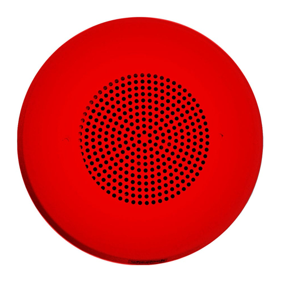
The Supervised Self-Amplified Speaker provides a choice of 6 different sound output levels and operates with audio input levels of
0.5 VRMS (e.g., from Wheelock's SALL-15S or any other 0.5V-RMS audio output source Listed for Fire Protective Signaling
Service) and 25 VRMS, all by means of selectable switch settings. The Low Profile design incorporates a high efficiency speaker for
maximum output at minimum power across a frequency range of 400Hz to 4000Hz, and features a sealed back construction for extra
protection and improved audibility. The appliance mounts onto a 4" square deep backbox with an extension ring. (See Mounting
Options.) All inputs are polarized for compatibility with standard reverse polarity supervision of circuit wiring via a Control Panel.
NOTE: All CAUTIONS and WARNINGS are identified by the symbol
WARNING: THE SPEAKER APPLIANCE IS A "FIRE ALARM DEVICE - DO NOT PAINT."
WARNING: PLEASE READ THESE INSTRUCTIONS CAREFULLY BEFORE USING THIS PRODUCT. THE
SUPERVISED SELF-AMPLIFIED SPEAKER MUST BE FIELD SET TO THE DESIRED SOUND OUTPUT LEVEL
BEFORE IT IS INSTALLED.
ACCORDANCE WITH THESE INSTRUCTIONS. INCORRECT SETTINGS WILL RESULT IN IMPROPER
PERFORMANCE AND MAY DAMAGE THE PRODUCT, WHICH COULD RESULT IN PROPERTY DAMAGE AND
SERIOUS INJURY OR DEATH TO YOU AND/OR OTHERS.
WARNING: CHECK THE MINIMUM AND MAXIMUM OUTPUT OF THE POWER SUPPLY AND STANDBY
BATTERY AND SUBTRACT THE VOLTAGE DROP FROM THE CIRCUIT WIRING RESISTANCE TO DETERMINE
THE APPLIED VOLTAGE TO THE APPLIANCES.
Copyright 2004 Wheelock, Inc. All rights reserved.
Thank you for using our products.
INSTALLATION INSTRUCTIONS
SUPERVISED SELF-AMPLIFIED SPEAKER
Supervised Self-Amplified Speaker
Supervised Self-Amplified Speaker
Supervised Self-Amplified Speaker
Supervised Self-Amplified Speaker
THIS IS DONE BY PROPERLY ADJUSTING A FOUR-POSITION SWITCH IN
. All warnings are printed in bold capital letters.
P84502 C
Sheet 1 of 6
Advertisement
Table of Contents

Summary of Contents for Wheelock SA-S70-R
- Page 1 The Supervised Self-Amplified Speaker provides a choice of 6 different sound output levels and operates with audio input levels of 0.5 VRMS (e.g., from Wheelock’s SALL-15S or any other 0.5V-RMS audio output source Listed for Fire Protective Signaling Service) and 25 VRMS, all by means of selectable switch settings. The Low Profile design incorporates a high efficiency speaker for maximum output at minimum power across a frequency range of 400Hz to 4000Hz, and features a sealed back construction for extra protection and improved audibility.
- Page 2 SPECIFICATIONS: Table 1A: Sound Output Level Sound Rated Reverberant dBA at 10 ft per UL 1480 for 0.5-V and 25-V Settings Level NOTE: See Table 3 Sound Output Level Selection for use of settings “A” and “B”. Power Input Voltage: 16.0 to 33.0 VDC, regulated Current Consumption: 120 mA RMS maximum...
- Page 3 Figure 2: SLIDE HERE FOR (0N) SLIDE HERE FOR (OFF) USE A SMALL SCREWDRIVER TO POS 1 CHANGE THE SWITCH POSITION. POS 2 POS 3 POS 4 Table 2: Audio Input Voltage Mode Selection Audio Input Voltage Mode Switch Settings (SW1) POS 1 0.5 V RMS 25 V RMS...
- Page 4 RESISTOR NOTE: All wiring must be all power-limited or all non-power-limited. *Refer to Sync Module instruction sheets SM (P83123), DSM (P83177) or Wheelock’s Power Supplies for additional information. MOUNTING PROCEDURES: CAUTION: Check that the installed product will have sufficient clearance and wiring room prior to installing backboxes and conduit, especially if sheathed multiconductor cable or 3/4"...
- Page 5 Although the limits shown for each mounting option comply with the National Electrical Code (NEC), Wheelock recommends use of the largest backbox option shown and the use of approved stranded field wires, whenever possible, to provide additional wiring room for easy installation and minimum stress on the product from wiring.
-
Page 6: Limited Warranty
(as determined by date code). Correction of defects by repair or replacement shall be at Wheelock's sole discretion and shall constitute fulfillment of all obligations under this warranty. THE FOREGOING LIMITED WARRANTY SHALL IMMEDIATELY TERMINATE IN THE EVENT ANY PART NOT FURNISHED BY WHEELOCK IS INSTALLED IN THE PRODUCT.


Need help?
Do you have a question about the SA-S70-R and is the answer not in the manual?
Questions and answers