Advertisement
Quick Links
273 Branchport Ave.
Long Branch, N.J. 07740
(800) 631-2148
www.wheelockinc.com
Use this product according to this instruction manual. Please keep this instruction manual for future reference.
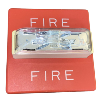
GENERAL:
Wheelock's Series RSSR Strobes can provide a non-synchronized strobe appliance when connected directly to a fire alarm control panel (FACP), or provide a
synchronized strobe appliance when used in conjunction with a Sync Module (SM), Dual Sync Module (DSM) or Wheelock's PS-12/24-8 Power Supply with
patented sync protocol. The RSSR Strobe appliances are UL Listed under Standard 1638 for Emergency Devices. The RSSR-2415C, RSSR-2475C and RSSR-
24110C strobes are intended for ceiling mount only and the RSSR-2415W, RSSR-2475W and RSSR-24110W strobes are intended for wall mount only, with the
backboxes specified in these instructions (See Mounting Options). The RSSR models have an integrated strobe mounting plate (SMP) that can be mounted to a
single-gang, double-gang, 4" backbox, 100mm European backbox or SHBB surface backbox. The strobe uses a xenon flashtube with solid state circuitry
enclosed in a polycarbonate lens to provide maximum visibility and reliability for effective visible signaling. All inputs are polarized for compatibility with
standard reverse polarity supervision of circuit wiring by an FACP.
WARNING:
PLEASE READ THESE INSTRUCTIONS CAREFULLY.
INSTRUCTIONS, CAUTIONS AND WARNINGS COULD RESULT IN IMPROPER APPLICATION, INSTALLATION AND/OR OPERATION OF
THESE PRODUCTS IN AN EMERGENCY SITUATION, WHICH COULD RESULT IN PROPERTY DAMAGE AND SERIOUS INJURY OR
DEATH TO YOU AND/OR OTHERS.
SPECIFICATIONS:
RSSR-2415C
RSSR-2415W
RSSR-2475C
RSSR-2475W
RSSR-24110C
RSSR-24110W
NOTES:
1.
Strobes will produce 1 flash per second over the "Regulated Voltage" range.
2.
All models are for indoor use with a temperature range of +32°F to +120°F (0°C to +49°C) and maximum humidity of 85% RH. The effect of shipping
and storage temperatures shall not adversely affect the performance of the appliance when it is stored in the original cartons and is not subjected to misuse
or abuse.
A7
A4
A2
A1
A6
When calculating the total currents use Table 3 to determine the highest value of RMS current for an individual strobe, then multiply these values by the total number of
strobes. Be sure to add the currents for any other appliances, including audible signaling appliances powered by the same source, and to include any required safety
factors.
NOTE: The maximum number of strobes on a single notification appliance circuit shall not exceed 50.
UL Voltage
DC
16-33VDC
FWR
CAUTION: These notification appliances are UL Listed as "Regulated". They are intended to be used with FACPs whose notification circuits are UL Listed as
"Regulated." These appliances shall not be used on UL Listed "Special Application" notification circuits unless the appliances are identified to be compatible in the
installation instructions of the FACP or unless the FACP is identified to be compatible in this instruction manual.
WARNING: THESE APPLIANCES WERE TESTED TO THE REGULATED VOLTAGE LIMITS OF 16.0-33.0 VOLTS FOR 24V MODELS USING
FILTERED DC OR UNFILTERED FULL-WAVE-RECTIFIED VOLTAGE. DO NOT APPLY VOLTAGE OUTSIDE OF THIS RANGE.
Copyright 2005 Wheelock, Inc. All rights reserved.
Thank you for using our products.
INSTALLATION INSTRUCTIONS
SERIES RSSR STROBE APPLIANCES
Table 1: UL Models and Ratings
Model
Regulated
Voltage
(VDC/VRMS)
24
24
24
24
24
24
Model
RSSR-2415C
A5
RSSR-2415W
RSSR-2475C
A3
RSSR-2475W
RSSR-24110C
RSSR-24110W
Table 3: UL Current Ratings (AMPS)
2415C/W
16-33VRMS
FAILURE TO COMPLY WITH ANY OF THE FOLLOWING
Voltage
Strobe Candela
Range
(VDC/VRMS)
16.0-33.0
16.0-33.0
16.0-33.0
16.0-33.0
16.0-33.0
16.0-33.0
Table 2: Candela at Various Angles Per UL 1638
Rated
Candela
A1
15.0cd
15
15.0cd
15
75.0cd
75
75.0cd
75
110.0cd
110
110.0cd
110
Maximum RMS Current Draw
2475C/W
0.090
0.315
0.145
0.480
Mounting
(cd)
Options
15
A,B,C,D
15
A,B,C,D
75
A,B,C,D
75
A,B,C,D
110
A,B,C,D
110
A,B,C,D
A2
A3
A4
A5
1.3
1.3
1.2
1.2
1.3
1.3
1.2
1.2
6.7
6.7
6.2
6.2
6.7
6.7
6.2
6.2
9.8
9.8
9.1
9.1
9.8
9.8
9.1
9.1
24110C/W
0.420
0.645
A6/A7
0.7
0.7
3.3
3.3
4.8
4.8
P83884 J
Sheet 1 of 4
Advertisement

Related Manuals for Wheelock RSSR-2415C


Summary of Contents for Wheelock RSSR-2415C
-
Page 1: Installation Instructions
GENERAL: Wheelock’s Series RSSR Strobes can provide a non-synchronized strobe appliance when connected directly to a fire alarm control panel (FACP), or provide a synchronized strobe appliance when used in conjunction with a Sync Module (SM), Dual Sync Module (DSM) or Wheelock’s PS-12/24-8 Power Supply with patented sync protocol. - Page 2 3/4" conduit fittings are used. Although the limits shown for each mounting option comply with the National Electrical Code (NEC), Wheelock recommends use of the largest backbox option shown and the use of approved stranded field wires, whenever possible, to provide additional wiring room for easy installation and minimum stress on the product from wiring.
- Page 3 STRONGLY RECOMMENDS THAT THE STROBES INSTALLED SHOULD NOT PRESENT A COMPOSITE FLASH RATE IN THE FIELD OF VIEW WHICH EXCEEDS FIVE (5) Hz AT THE OPERATING VOLTAGE OF THE STROBES. WHEELOCK ALSO STRONGLY RECOMMENDS THAT THE INTENSITY AND COMPOSITE FLASH RATE OF INSTALLED STROBES COMPLY WITH LEVELS ESTABLISHED BY APPLICABLE LAWS, STANDARDS, REGULATIONS, CODES AND GUIDELINES.
- Page 4 (as determined by date code). Correction of defects by repair or replacement shall be at Wheelock's sole discretion and shall constitute fulfillment of all obligations under this warranty. THE FOREGOING LIMITED WARRANTY SHALL IMMEDIATELY TERMINATE IN THE EVENT ANY PART NOT FURNISHED BY WHEELOCK IS INSTALLED IN THE PRODUCT.
Need help?
Do you have a question about the RSSR-2415C and is the answer not in the manual?
Questions and answers