Advertisement
273 Branchport Ave.
Long Branch, N.J. 07740
(800) 631-2148
www.wheelockinc.com
Use this product according to this instruction manual. Please keep this instruction manual for future reference.
GENERAL:
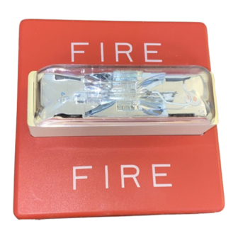
Wheelock's Series RSS and RSSP Strobes can provide a non-synchronized strobe appliance when connected directly to a Fire Alarm
Control Panel (FACP), or provide a synchronized strobe appliance when used in conjunction with a Sync Module (SM), Dual Sync
Module (DSM) or Power Supply (PS-12/24-8). The Series RSS and RSSP Strobe Appliances are UL Listed under Standard 1971
(Signaling Devices for the Hearing Impaired) for indoor fire protection service. These Strobes are listed for wall mount only, with the
backboxes specified in these instructions (See Mounting Options). RSS models have an integrated Strobe Mounting Plate (SMP) that
can be mounted to a single-gang, double-gang, 4" backbox, 100mm European backbox or SHBB surface backbox. The strobes use a
Xenon flashtube with solid state circuitry enclosed in a rugged Lexan lens to provide maximum visibility and reliability for effective
visible signaling. All inputs are polarized for compatibility with standard reverse polarity supervision of circuit wiring by the FACP.
NOTE: All CAUTIONS and WARNINGS are identified by the symbol
WARNING: THE RSS STROBE APPLIANCE IS A "FIRE ALARM DEVICE - DO NOT PAINT."
WARNING:
READ THESE INSTRUCTIONS CAREFULLY.
FOLLOWING INSTRUCTIONS, CAUTIONS AND WARNINGS COULD RESULT IN IMPROPER APPLICATION,
INSTALLATION AND/OR OPERATION OF THESE PRODUCTS IN AN EMERGENCY SITUATION, WHICH COULD
RESULT IN PROPERTY DAMAGE AND SERIOUS INJURY OR DEATH TO YOU AND/OR OTHERS.
SPECIFICATIONS:
Table 1: Ratings Per UL 1971
Model
Regulated
Voltage
VDC/VRMS
RSS-2415W
24
RSSP-2415W
24
RSS-2430W
24
RSSP-2430W
24
RSS-2475W
24
RSSP-2475W
24
RSS-24110W
24
RSSP-24110W
24
RSS-1215W
12
RSSP-1215W
12
NOTE:
THE MAXIMUM WIRE IMPEDANCE BETWEEN STROBES SHALL NOT EXCEED 35 OHMS.
MAXIMUM NUMBER OF STROBES ON A SINGLE NOTIFICATION APPLIANCE CIRCUIT SHALL NOT EXCEED 47.
WARNING: THESE APPLIANCES WERE TESTED TO THE OPERATING VOLTAGE LIMITS OF 16-33 VOLTS
FOR 24V MODELS AND 8-17.5 VOLTS FOR 12V MODELS USING FILTERED (DC) OR UNFILTERED FULL-WAVE
RECTIFIED (FWR). DO NOT APPLY 80% AND 110% OF THESE VOLTAGE VALUES FOR SYSTEM OPERATION.
WARNING: CHECK THE MINIMUM AND MAXIMUM OUTPUT OF THE POWER SUPPLY AND STANDBY
BATTERY AND SUBTRACT THE VOLTAGE DROP FROM THE CIRCUIT WIRING RESISTANCE TO DETERMINE
THE APPLIED VOLTAGE TO THE STROBES.
Copyright 2001 Wheelock, Inc. All rights reserved.
Thank you for using our products.
INSTALLATION INSTRUCTIONS
SERIES RSS AND RSSP STROBE APPLIANCES
(WALL MOUNT VERSIONS)
Voltage
Strobe
Mounting
Range Limit
Candela
Options
VDC/VRMS
(CD)
16.0-33.0
15
A,B,C,D
16.0-33.0
15
16.0-33.0
30
A,B,C,D
16.0-33.0
30
16.0-33.0
75
A,B,C,D
16.0-33.0
75
16.0-33.0
110
A,B,C,D
16.0-33.0
110
8.0-17.5
15
A,B,C,D
8.0-17.5
15
. All warnings are printed in bold capital letters.
FAILURE TO COMPLY WITH ANY OF THE
Audibles/Speakers for RSSP Strobe/Plate
Product
Multitone Appliances
Motor Bells
Speakers
E,F
Chimes
E,F
NOTES:
E,F
1. Strobes will produce 1 flash per second over the "Regulated
E,F
Voltage" range.
2. All models are UL Listed for indoor use with a temperature
E,F
range of +32
humidity of 85% RH.
Table 1A.
Series
AMT, MT, MT4
MB-G6/G10
ET-1010/1070/1080, ET70,
E7025/7070, E70
CH70
o
o
o
o
F to +120
F (0
C to +49
C) and maximum
THE
P84022 F
Sheet 1 of 6
Advertisement
Table of Contents

Related Manuals for Wheelock RSS-1215W


Summary of Contents for Wheelock RSS-1215W
- Page 1 GENERAL: Wheelock’s Series RSS and RSSP Strobes can provide a non-synchronized strobe appliance when connected directly to a Fire Alarm Control Panel (FACP), or provide a synchronized strobe appliance when used in conjunction with a Sync Module (SM), Dual Sync Module (DSM) or Power Supply (PS-12/24-8).
- Page 2 Table 2A: Current Ratings (AMPS) for 24VDC Models Rated Average Current Voltage 2415W 2430W 2475W 24110W MEAN MEAN MEAN MEAN 16.0VDC 0.072 0.090 0.125 0.143 0.215 0.257 0.276 0.327 24.0VDC 0.053 0.079 0.085 0.113 0.140 0.200 0.169 0.256 33.0VDC 0.045 0.072 0.069 0.103...
- Page 3 When calculating the total average, peak or inrush currents: Use Table 2A and 2B to determine the highest value of “Rated Average Current” for an individual strobe (across the expected operating voltage range of the strobe) to determine the highest value of “Rated Inrush Current”...
-
Page 4: Mounting Options
Although the limits shown for each mounting option comply with the National Electrical Code (NEC), Wheelock recommends use of the largest backbox option shown and the use of approved stranded field wires, whenever possible, to provide additional wiring room for easy installation and minimum stress on the product from wiring. - Page 5 DESCRIBING THE PRODUCT FOR USE IN PROMOTIONAL OR ADVERTISING CLAIMS, OR FOR ANY OTHER USE, INCLUDING DESCRIPTION OF THE PRODUCT'S APPLICATION, OPERATION, INSTALLATION AND TESTING IS USED AT THE SOLE RISK OF THE USER AND WHEELOCK WILL NOT HAVE ANY LIABILITY FOR SUCH USE. P84022 F...
-
Page 6: Limited Warranty
ON ANY CLAIM OF ANY KIND SHALL CEASE IMMEDIATELY UPON THE INSTALLATION IN THE PRODUCT OF ANY PART NOT FURNISHED BY WHEELOCK. IN NO EVENT SHALL WHEELOCK BE LIABLE FOR ANY CLAIM OF ANY KIND UNLESS IT IS PROVEN THAT OUR PRODUCT WAS A DIRECT CAUSE OF SUCH CLAIM. FURTHER, IN NO EVENT, INCLUDING IN THE CASE OF A CLAIM OF NEGLIGENCE, SHALL WHEELOCK BE LIABLE FOR INCIDENTAL OR CONSEQUENTIAL DAMAGES.
Need help?
Do you have a question about the RSS-1215W and is the answer not in the manual?
Questions and answers