Advertisement
273 Branchport Ave.
Long Branch, N.J. 07740
(800) 631-2148
www.wheelockinc.com
Use this product according to this instruction manual. Please keep this instruction manual for future reference.
GENERAL:
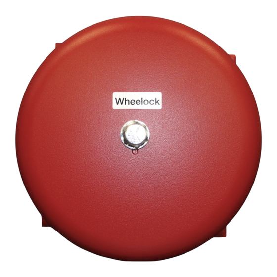
Series MB Motor Bells are UL Listed for Fire Protective Service with the exception of the 6VDC Motor Bell which is UL approved
for general signaling use. The Motor Bell Series incorporates a high torque permanent magnet motor to provide high output with
minimum current draw. Integral MOV suppression is provided to minimize RFI and turn-off transients. In-out wiring terminals and a
built-in trim plate, for semi-flush mounting, are provided for easy installation. The Motor Bell Series is available in 6VDC with a 6"
bell shell and 12VDC or 24VDC with either a 6" or 10" bell shell.
NOTE: All CAUTIONS and WARNINGS are identified by the symbol
WARNING: PLEASE READ THESE INSTRUCTIONS CAREFULLY. FAILURE TO COMPLY WITH ANY OF THE
FOLLOWING INSTRUCTIONS, CAUTIONS AND WARNINGS COULD RESULT IN IMPROPER APPLICATION,
INSTALLATION AND/OR OPERATION OF THESE PRODUCTS IN AN EMERGENCY SITUATION, WHICH COULD
RESULT IN PROPERTY DAMAGE AND SERIOUS INJURY OR DEATH TO YOU AND/OR OTHERS.
SPECIFICATIONS:
Model
Gong Size
MB-G6-6
6"
MB-G6-12
6"
MB-G10-12
10"
MB-G6-24
6"
MB-G10-24
10"
WARNING: FOR UL APPLICATIONS THESE APPLIANCES WERE TESTED TO THE OPERATING VOLTAGE
LIMITS OF 16-33 VOLTS FOR 24V MODELS, 8-17.5V FOR 12V MODELS, OR 4.2-7.8V FOR 6V MODELS USING
FILTERED (DC) OR UNFILTERED FULL-WAVE-RECTIFIED (FWR). DO NOT APPLY 80% AND 110% OF THESE
VOLTAGE VALUES FOR SYSTEM OPERATION.
WARNING: MAKE SURE THAT THE TOTAL RMS CURRENT REQUIRED BY ALL APPLIANCES THAT ARE CONNECTED
TO THE SYSTEM'S PRIMARY AND SECONDARY POWER SOURCES, NAC CIRCUITS, SM, DSM SYNC MODULES OR
WHEELOCKS POWER SUPPLIES DO NOT EXCEED THE POWER SOURCES' RATED CAPACITY OR THE CURRENT RATINGS
OF ANY FUSES ON THE CIRCUITS TO WHICH THESE APPLIANCES ARE WIRED. OVERLOADING POWER SOURCES OR
EXCEEDING FUSE RATINGS COULD RESULT IN LOSS OF POWER AND FAILURE TO ALERT OCCUPANTS DURING AN
EMERGENCY, WHICH COULD RESULT IN PROPERTY DAMAGE AND SERIOUS INJURY OR DEATH TO YOU AND/OR
OTHERS.
When calculating the total currents: Use Table 1 to determine the highest value of "RMS Current" for an individual bell (across the
expected operating voltage range of the bell), then multiply these values by the total number of bells; be sure to add the currents for
any other appliances, including audible signaling appliances, powered by the same source and include any required safety factors.
If the peak current exceeds the power supplies' peak capacity, the output voltage provided by the power supplies may drop below the
listed voltage range of the appliances connected to the supply and the voltage may not recover in some types of power supplies. For
example, an auxiliary power supply that lacks filtering at its output stage (either via lack of capacitance and/or lack of battery backup
across the output) may exhibit this characteristic.
Copyright 2004 Wheelock, Inc. All rights reserved.
Thank you for using our products.
INSTALLATION INSTRUCTIONS
Table 1: UL Listed Models and Ratings
Voltage Range
Maximum RMS Current Draw
(VDC/VRMS)
DC
4.2-7.8
0.130
8.0-17.5
0.090
8.0-17.5
0.090
16.0-33.0
0.040
16.0-33.0
0.040
SERIES MB BELLS
. All warnings are printed in bold capital letters.
FWR
0.160
0.110
0.110
0.056
0.056
Reverberant dBA Per UL 464
Min
Nom
Max
75
82
85
79
85
88
82
88
91
82
85
88
82
88
91
Mounting
Options
A,B,C,D
A,B,C,D
A,B,C,D
A,B,C,D
A,B,C,D
P81960 J
Sheet 1 of 4
Advertisement
Table of Contents

Related Manuals for Wheelock MB Series


Summary of Contents for Wheelock MB Series
- Page 1 (either via lack of capacitance and/or lack of battery backup across the output) may exhibit this characteristic. Copyright 2004 Wheelock, Inc. All rights reserved. P81960 J Sheet 1 of 4...
- Page 2 WIRING DIAGRAM: Figure 1: FROM PRECEDING TO NEXT BELL SIGNAL OR FIRE ALARM OR END OF LINE CONTROL PANEL (FACP) RESISTOR (EOLR) MOUNTING INFORMATION: Mounting Options Are Shown In The Following Diagrams: 1. Unscrew the center bolt to remove the bell shell. (See Mounting Procedures Note 2 .) 2.
- Page 3 : (Mounting Plates and backboxes ordered separately - specify color) MOUNTING OPTIONS SEMI-FLUSH MOUNTING SURFACE MOUNTING STANDARD STANDARD 4" SQUARE BACKBOX BACKBOX MAXIMUM NUMBER OF CONDUCTORS MAXIMUM NUMBER OF CONDUCTORS AWG #18 AWG #16 AWG #14 AWG #12 AWG #18 AWG #16 AWG #14 AWG #12 OUTDOOR MOUNTING CONCEALED CONDUIT MOUNTING WEATHER RESISTANT...
- Page 4 (as determined by date code). Correction of defects by repair or replacement shall be at Wheelock's sole discretion and shall constitute fulfillment of all obligations under this warranty. THE FOREGOING LIMITED WARRANTY SHALL IMMEDIATELY TERMINATE IN THE EVENT ANY PART NOT FURNISHED BY WHEELOCK IS INSTALLED IN THE PRODUCT.
Need help?
Do you have a question about the MB Series and is the answer not in the manual?
Questions and answers