InFocus IN5542 Service Manual
Multimedia lcd projector
Hide thumbs
Also See for IN5542:
- User manual (78 pages) ,
- User manual (26 pages) ,
- User manual (52 pages)
Table of Contents
Advertisement
SERVICE MANUAL
Warning
The technical information and parts shown in this
manual are not to be used for: the development,
design, production, storage or use of nuclear, chemical,
biological or missile weapons or other weapons of
mass destruction; or military purposes; or purposes that
endanger global safety and peace. Moreover, do not
sell, give, or export these items, or grant permission for
use to parties with such objectives. Forward all inquiries
to the SUPPLIER.
Be sure to read this manual before servicing. To assure safety from fire, electric shock, injury, harmful
radiation and materials, various measures are provided in this Multimedia LCD Projector. Be sure to
read cautionary items described in the manual to maintain safety before servicing.
1. When replace the lamp, to avoid burns to your fingers. The lamp becomes too hot.
2. Never touch the lamp bulb with a finger or anything else. Never drop it or give it a shock. They may
cause bursting of the bulb.
3. This projector is provided with a high voltage circuit for the lamp. Do not touch the electric parts of
power unit (circuit) and power unit (ballast), after turn on the projector.
4. Do not touch the exhaust fan, during operation.
5. The LCD module assembly is likely to be damaged. If replacing to the LCD PRISM assembly, do
not hold the FPC of the LCD module assembly.
6. Use the cables which are included with the projector or specified.
1. Features ------------------------------------------------------ 2
2. Specifications ----------------------------------------------- 2
3. Names of each part ---------------------------------------- 3
4. Adjustment --------------------------------------------------- 6
5. Troubleshooting ------------------------------------------ 13
6. Service points --------------------------------------------- 20
7. Wiring diagram -------------------------------------------- 49
SPECIFICATIONS AND PARTS ARE SUBJECT TO CHANGE FOR IMPROVEMENT.
Multimedia LCD Projector
IN5542
IN5544
Caution
Service Warning
Contents
8. Disassembly diagram ----------------------------------- 60
9. Replacement parts list ---------------------------------- 72
10.RS-232C communication ------------------------------- 74
11. Block diagram --------------------------------------------- 87
12. Connector connection diagram ----------------------- 88
13.Basic circuit diagram ------------------------------------ 89
March 2012
(P6X)
(P6WX)
Advertisement
Table of Contents

Related Manuals for InFocus IN5542


Summary of Contents for InFocus IN5542
-
Page 1: Table Of Contents
IN5542 (P6X) IN5544 (P6WX) SERVICE MANUAL Warning The technical information and parts shown in this manual are not to be used for: the development, design, production, storage or use of nuclear, chemical, biological or missile weapons or other weapons of mass destruction;... -
Page 2: Features
IN5542 ( P6X ) / IN5544 ( P6WX ) 1. Features • High Brightness • Remote Control Via Your Web Browser •Mechanical lens shutter • Low Noise • Rich Connectivity 2. Specifications Drive system TFT active matrix Liquid IN5542 : 33mm(1.3 type) -
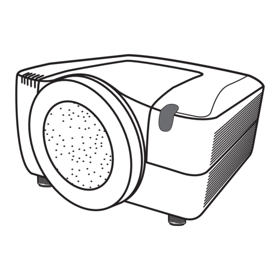
Page 3: Names Of Each Part
IN5542 ( P6X ) / IN5544 ( P6WX ) 3. Names of each part Projector Front ring Front cover (1) Dust protector (2) Remote sensors (x 2) (3) Exhaust vents (4) Filter cover The filter unit and intake vent are inside. -
Page 4: Control Panel
IN5542 ( P6X ) / IN5544 ( P6WX ) Control panel (1) STANDBY/ON button STANDBY/ON (2) Cursor buttons ( ▲/▼/◄/► ) (3) MENU button (4) COMPUTER button (5) VIDEO button The indicator (6) DIGITAL button (7) LENS SHIFT button will light in... -
Page 5: Remote Control
IN5542 ( P6X ) / IN5544 ( P6WX ) Remote control (1) Laser pointer It is a beam outlet. (2) LASER INDICATOR LASER INDICATOR (3) LASER button STANDBY/ON MY SOURCE COMPUTER (4) STANDBY/ON button VIDEO (5) ID (1-4) button ID 1... -
Page 6: Adjustment
IN5542 ( P6X ) / IN5544 ( P6WX ) 4. Adjustment 4-1 Before adjusting 4-1-1 Selection of adjustment When any parts in the table 4-1 are changed, choose the proper adjusting items with the chart. Table 4-1: Relation between the replaced part and adjustment... - Page 7 IN5542 ( P6X ) / IN5544 ( P6WX ) 4-2 Flicker adjustment (V.COM adjustment) Test pattern for the adjustment Adjustment procedure 1. Use DAC-P - V.COM - R: in the FACTORY MENU to adjust so that the flicker at the center of 128/255 the screen is less than the flicker at the periphery.
- Page 8 IN5542 ( P6X ) / IN5544 ( P6WX ) 4-4 PSIG adjustment (vertical bars adjustment) Test pattern for the adjustment Adjustment procedure 1. Make this adjustment after completing the ad- /255 justment in the section 4-3. /255 2. Use DAC - P_PSIG - R : in the FACTORY MENU and use it so that vertical bars are minimized.
- Page 9 IN5542 ( P6X ) / IN5544 ( P6WX ) 4-6 Color uniformity adjustments Preparations 1. Perform these adjustments after the adjustments 5. Adjustment point No.1 should not be adjusted, described in the section 4-5. because it controls the brightness of the entire 2.
- Page 10 IN5542 ( P6X ) / IN5544 ( P6WX ) Adjustment procedure 1 (When a color differential meter is used) Note: Since excessive correction may lead to a 1. First adjust the [MID-1] tone [G:]. correction data overview during internal 2. Select adjustment point [No.2][G:].
- Page 11 IN5542 ( P6X ) / IN5544 ( P6WX ) Adjustment procedure 2 (visual inspection) same color as measurement point [No.1]. 1. First adjust [MIN] tone [G:]. Adjustment technique: 2. Select [No.2] [G:]. First, adjust [B:] of the point whose color is to...
-
Page 12: Using The Functions For The Lens
IN5542 ( P6X ) / IN5544 ( P6WX ) 4-7 Adjusting the zoom and focus Using the functions for the lens ZOOM / FOCUS Press the ZOOM / FOCUS button. The ZOOM / FOCUS dialog will appear. Adjust the zoom / focus using the ◄/►... -
Page 13: Troubleshooting
IN5542 ( P6X ) / IN5544 ( P6WX ) 5. Troubleshooting Check points PW assembly LED PW assembly REMOTE DY05 DY04 DY02 DY03 DY01 (SHUTTER) (SECURITY) (LAMP) (TEMP) (POWER) EW03 EW05 E305 EW06 E802 EW04 E811 EW01 EW02 P701 P501... - Page 14 IN5542 ( P6X ) / IN5544 ( P6WX ) Power can not be turned on *: Be sure to unplug the power cord before measuring resistance. Measure voltage resistance* between supplied at pins 0Ω pins (1) and (11), between pins...
- Page 15 IN5542 ( P6X ) / IN5544 ( P6WX ) Lamp does not light *: Be sure to unplug the power cord before measuring resistance. Wait 20 seconds What is the state of Light LAMP indicator DY02 during operation? Not light...
- Page 16 IN5542 ( P6X ) / IN5544 ( P6WX ) Picture is not displayed when the RGB signal is input Confirm the splash screen the LCD Panels CPC57 connector and the user menu displayed connection to the MAIN correctly? board. PWB assembly MAIN...
- Page 17 IN5542 ( P6X ) / IN5544 ( P6WX ) Can not control to RS-232C The check after parts change 1. PC power supply OFF 2. Connection of cable 3. Projector starting 4. PC starting Check the *When not operating : RS-232C cable.
- Page 18 IN5542 ( P6X ) / IN5544 ( P6WX ) Can’t communicate with computer via LAN port. Check at operating mode Does the Lamp Is the computer Make sure NETWORK on lower right of the connected with the hardware LAN connector light...
- Page 19 IN5542 ( P6X ) / IN5544 ( P6WX ) Have any bended Has the FWO1 pins of connecters of the adapter or (fuse, 1.75A) of the main relay boards made short-circuited? board blown out? 1) According to failed Change main board...
-
Page 20: Service Points
IN5542 ( P6X ) / IN5544 ( P6WX ) 6. Service points 6-1 Lead free solder [CAUTION] This product uses lead free solder (unleaded) to help preserve the environment. Please read these instructions before attempting any soldering work. CAUTION Always wear safety glasses to prevent fumes or molten solder from getting into the eyes. Lead free solder can splatter at high temperatures (600˚C). - Page 21 IN5542 ( P6X ) / IN5544 ( P6WX ) 6-2 Before Replacing The LCD Prism You should not replace separately the parts of the liquid crystal LCD prism because it works properly only when used together. Therefore, regarding these parts, you can either replace part, LCD prism assembly, or send the whole unit LCD prism assembly back to the SUPPLIER, where we will replace the malfunctioning part, recondition the device and send it back to you.
- Page 22 IN5542 ( P6X ) / IN5544 ( P6WX ) 6-3-1 Replacement of P.O.Filter-IN (1) Remove a hex head screw and detach a PO.filter you will replace. (2) Attach a new PO.Filter with a hex head screw lightly. Pay attention not to make your finger or other components touch to the surface of the glass.
- Page 23 IN5542 ( P6X ) / IN5544 ( P6WX ) 6-3-2 Replacement of P.O.Filter-OUT (1) Detach the LCD/PRISM ass'y by following the procedure on the next page. Make sure not to daamge optical parts, especially the glass part of the panel and the P.O.Filter-IN.
- Page 24 IN5542 ( P6X ) / IN5544 ( P6WX ) 6-4 Cleaning up dust from panels and optical filters 1. Preparation Please prepare cleaning tools and materials as follows. And prepare relatively clean room not to work in additional dust, while removing operation.
- Page 25 IN5542 ( P6X ) / IN5544 ( P6WX ) 3. Maintenance point for LCD/PRISM side (1) Clean the LCD panel surface with Swab. (2) Insert Swab between LCD panel and PRISM when you clean the back surface of LCD panel and Optical filter.
- Page 26 IN5542 ( P6X ) / IN5544 ( P6WX ) 6-5 Battery WARNING Be careful of handling batteries, since a battery can cause explosion, cracking or leakage that could result in a fire, injury, or environment pollution. . Use only the specified batteries. Do not use batteries of different types.
- Page 27 IN5542 ( P6X ) / IN5544 ( P6WX ) 1. Set the lens shift position to center. Then, turn the projector off, and unplug the power cord. Allow the projector cool sufficiently. 2. After making sure that the projector has cooled adequately, turn the front ring, and remove.
-
Page 28: Changing The Frequency Of Remote Control Signal
IN5542 ( P6X ) / IN5544 ( P6WX ) 6-5-2 Putting batteries into the remote control • Use two new batteries of the specified type: HITACHI MAXELL or HITACHI MAXELL ENERGY part number AA Alkaline (LR6 or R6P). 1. Remove the battery cover. -
Page 29: Filter Unit
IN5542 ( P6X ) / IN5544 ( P6WX ) 6-6 Filter unit To keep inside ventilation normal, keep a spare and replace the filter unit periodically, although frequent replacement is not needed for this product. The following walks you through the steps to replace the filter unit. - Page 30 IN5542 ( P6X ) / IN5544 ( P6WX ) 6-7 Lamp A worn out lamp bulb could burn or burst. It is recommended to keep a spare lamp unit on hand and to replace the lamp unit when the projected image darkens or color reproduction becomes poor.
-
Page 31: Lamp Warning
IN5542 ( P6X ) / IN5544 ( P6WX ) WARNING Lamp warning HIGH TEMPERATURE HIGH PRESSURE HIGH VOLTAGE WARNING ►The projector uses a high-pressure mercury glass lamp. The lamp can break with a loud bang, or burn out, if jolted or scratched, handled while hot, or worn over time. -
Page 32: Replacing The Lens
IN5542 ( P6X ) / IN5544 ( P6WX ) 6-8 Lens CAUTION Important Safety Instructions Supplie (Always follow these instructions.) The distance of projection may not allow focusing on the peripheral Please read this section on important safety instructions before replacing The followin area of the screen. -
Page 33: Supplied Accessories
IN5542 ( P6X ) / IN5544 ( P6WX ) Supplied Accessories he peripheral The following accessories are included with each lens. nter and the Lens Model Supplied accessories Lens Model Supplied accessories Ultra short throw zoom lens Standard zoom lens... -
Page 34: Projection Distance
IN5542 ( P6X ) / IN5544 ( P6WX ) Projection Distance Unit: inch Model LENS-067 LENS-066 LENS-065 LENS-062 Panel aspect ratio Panel aspect ratio Panel aspect ratio Panel aspect ratio Diagonal Screen Size 17:10 17:10 17:10 17:10 [inch] 10.2 12.7 1000 15.2... - Page 35 IN5542 ( P6X ) / IN5544 ( P6WX ) ■ Lens replacement should be performed by a service engineer. ■ When changing the lens, place the LCD projector right way up on a horizontal surface. Do not change the lens with the projector facing upwards or downwards or when the projector is suspended.
- Page 36 IN5542 ( P6X ) / IN5544 ( P6WX ) wnwards or when Projector Attaching the LENS-067/LENS-066/LENS-065 Lens When Unpacking the LCD Projector 1. Lens attachment is completed. 6. Attaching the optional parts (3) Protector Follow the procedures in step 1 through...
- Page 37 IN5542 ( P6X ) / IN5544 ( P6WX ) Changing from an LENS-062/LENS-068/LENS-064/LENS-063 Lens to a LENS-067/LENS-066/LENS-065 Lens Changing fro 1. Disassembling the main unit parts (1) 8. Attaching the lens (2) 1. Removing the option Front ring Unscrew the front ring.
- Page 38 IN5542 ( P6X ) / IN5544 ( P6WX ) ENS-065 Lens Changing from a LENS-067/LENS-066/LENS-065 Lens to an LENS-062/LENS-068/LENS-064/LENS-063 Lens 1. Removing the optional parts (1) 8. Removing the lens (2) (LENS-066/LENS-065 only) Support the lens and remove the lens from Protector Rotate the protector 90°...
- Page 39 IN5542 ( P6X ) / IN5544 ( P6WX ) Flange-back Adjustment (LENS-067 only) (The two blinders and two protectors are not supplied with the LENS-067 lens.) 1. Check the surrounding focus 11. Fix the flange-back 7. Insert the FB adjustment pin...
-
Page 40: Other Care
9. Prepare for flange-back adjustment One setscrew Project the image for adjustment from the IN5542 ( P6X ) / IN5544 ( P6WX ) LCD projector onto the screen. Move the FB adjustment pin slowly clockwise or Counterclockwise 7 lens.) counterclockwise and adjust the flange-... - Page 41 IN5542 ( P6X ) / IN5544 ( P6WX ) 6-10 Notice of AUTO adjustment Use of AUTO adjustment with the image through RGB input optimizes V_POSI, H_POSI, and H_PHASE automatically. In case that projected image has dark tone around its peripheral, AUTO operation sometimes makes arti- facts in the image, shifts capture area and so on.
- Page 42 IN5542 ( P6X ) / IN5544 ( P6WX ) 6-11 How to inactivate the security functions This projector is equipped with security functions. (1)MyScreen PASSWORD The MyScreen PASSWORD function can be used to prohibit access to the MyScreen function and prevent the currently registered MyScreen image from being overwritten.
- Page 43 2. Send InFocus servicing provider the Inquiring code (10 digits) to inquire the correct PIN code. 3. While the PIN BOX is displayed, enter the correct PIN CODE that InFocus servicing provider informed. 4. Open menu and select “TURN OFF” from the PIN LOCK items in the SECURITY menu. Then the PIN BOX menu appears.
- Page 44 IN5542 ( P6X ) / IN5544 ( P6WX ) 6-13 Related Messages When the unit's power is on, messages such as those shown below may be displayed. When any such message is displayed on the screen, please follow the instructions described below.
-
Page 45: Regarding The Indicator Lamps
IN5542 ( P6X ) / IN5544 ( P6WX ) Regarding the indicator lamps Lighting and blinking of the POWER indicator, the TEMP indicator, the LAMP indicator, the SECURITY indicator and the SHUTTER indicator have the meanings as described in the table below. Please follow the instructions within the table. - Page 46 IN5542 ( P6X ) / IN5544 ( P6WX ) Description POWER TEMP LAMP SECURITY SHUTTER The cooling fan is not operating. Please turn the power off, and allow the projector to cool down at least 20 minutes. After the projector has...
- Page 47 IN5542 ( P6X ) / IN5544 ( P6WX ) 6-14 HIDDEN SERVICE MENU How to display the OSD for “HIDDEN SERVICE MENU” set up. HIDDEN SERVICE AIR-SENSOR EXECUTE By the control panel * By the remote control transmitter LAMP ALARM NONE 1.
- Page 48 IN5542 ( P6X ) / IN5544 ( P6WX ) 6-16 Reset of the Network Web password / User ID, Network Control password ATTENTION : Performing this operation initializes the network settings. If the projector has the customized settings in the network, make a note of the network settings to restore them before this operation.
-
Page 49: Wiring Diagram
IN5542 ( P6X ) / IN5544 ( P6WX ) 7. Wiring diagram... - Page 50 IN5542 ( P6X ) / IN5544 ( P6WX )
- Page 51 IN5542 ( P6X ) / IN5544 ( P6WX )
- Page 52 IN5542 ( P6X ) / IN5544 ( P6WX )
- Page 53 IN5542 ( P6X ) / IN5544 ( P6WX )
- Page 54 IN5542 ( P6X ) / IN5544 ( P6WX )
- Page 55 IN5542 ( P6X ) / IN5544 ( P6WX )
- Page 56 IN5542 ( P6X ) / IN5544 ( P6WX )
- Page 57 IN5542 ( P6X ) / IN5544 ( P6WX )
- Page 58 IN5542 ( P6X ) / IN5544 ( P6WX )
- Page 59 IN5542 ( P6X ) / IN5544 ( P6WX )
-
Page 60: Disassembly Diagram
IN5542 ( P6X ) / IN5544 ( P6WX ) 8. Disassembly diagram M:Meter screw T:Tapping screw (Notice1) (Notice7) (Notice2) (Notice4) (Notice13) Enlargement (Notice13) 36 3 (Notice4) (Notice4) (Notice7) (Notice4) (Notice4) Enlargement [ PWB assembly MAIN ] Enlargement [ Rear Terminal ]... - Page 61 IN5542 ( P6X ) / IN5544 ( P6WX ) [ OPT unit / LAMP unit / Exhaust fan for LAMP unit [ LCD/PRISM assembly ] / Exhaust fan for POWER unit around ] < Top view > G-out1 G-out2 (Notice5)
- Page 62 IN5542 ( P6X ) / IN5544 ( P6WX ) Notice CAUTION • Only Serviceman is allowed to do these works. • Put projector on stable and horizontal ground when you do there works. Note When you assemble/disassemble the projector, put the projector on the rubber plate (P/N: MQ03421) to prevent the projector casing from being distorted.
- Page 63 IN5542 ( P6X ) / IN5544 ( P6WX ) When assembling a. Tighten 2 screws on upper case, 2 screws on front, 4screws on back, 4screws on left side and 2 screws on right side to detach upper case. (Refer disassembling procedure.) b.
- Page 64 IN5542 ( P6X ) / IN5544 ( P6WX ) 3. Assembling and Disassembling the power unit block. a. Assembling and Disassembling the ballast. ATTENTION Note the Heatsinks have the Sharp edge, at the time you connect/disconnect CNPFC. Assembly Disassembly Never loosens A, B or C.
- Page 65 IN5542 ( P6X ) / IN5544 ( P6WX ) b. Assembling and Disassembling the power unit fan. Assembly Disassembly c. Assembling and Disassembling the power unit block. Assembly Disassembly Attach [A] over [B] in this point. Tighten this screw first.
- Page 66 IN5542 ( P6X ) / IN5544 ( P6WX ) 4. Assembling and Disassembling the rear cover. a. Assembling and Disassembling the input board unit. Slit PWB assembly REMOTE B PWB assembly INPUT A PWB assembly INPUT B PWB assembly INPUT C...
- Page 67 IN5542 ( P6X ) / IN5544 ( P6WX ) c. Attach input board fan to rear cover. Detach input board fan from rear cover. Wire leads so they CAUTION aren't put on this lib. Clamp IRIS cable in rear cover after you installed optics engine.
- Page 68 IN5542 ( P6X ) / IN5544 ( P6WX ) 6. Assembling and Disassembling the exhaust FAN. Printed surface 7. Attaching and Detaching LED board and Out sensor. • Attach 4 cushons to LED board. • Attach LED board to bracket.
- Page 69 IN5542 ( P6X ) / IN5544 ( P6WX ) 8. Assembling and Disassembling the Duct. a. Assembling and Disassembling the bottom case. Use 3x16 (long) screws. • Pass fan cable between duct wall and fan, and draw out cable from slit.
- Page 70 IN5542 ( P6X ) / IN5544 ( P6WX ) 9. Assembling and Disassembling the PBS fan. disassembly assembly CAUTION Take care for exhaust direction and combination between fan and bracket. 10. Attaching the lamp fan. Use 3x16 (long) screws. 11. Dettaching the lamp house.
- Page 71 IN5542 ( P6X ) / IN5544 ( P6WX ) 12. Dettaching the Shift cover. Shift cover Remove this cushion before you detach the shift cover. When attach/detach shift cover, never make it touch motor terminal. 13. Assembling the Control unit.
-
Page 72: Replacement Parts List
IN5542 ( P6X ) / IN5544 ( P6WX ) 9. Replacement Parts list PRODUCT SAFETY NOTE : Components marked with a have special characteristics important to safety. Before replacing any of there components, read carefully, the PRODUCT SAFETY NOTICE of this Service Manual. Don't degrade the safety of the projector through improper servicing. - Page 73 IN5542 ( P6X ) / IN5544 ( P6WX ) PRODUCT SAFETY NOTE : Components marked with a have special characteristics important to safety. Before replacing any of there components, read carefully, the PRODUCT SAFETY NOTICE of this Service Manual. Don't degrade the safety of the projector through improper servicing.
-
Page 74: Rs-232C Communication
IN5542 ( P6X ) / IN5544 ( P6WX ) 10. RS-232C communication... - Page 75 IN5542 ( P6X ) / IN5544 ( P6WX )
- Page 76 IN5542 ( P6X ) / IN5544 ( P6WX )
- Page 77 IN5542 ( P6X ) / IN5544 ( P6WX )
- Page 78 IN5542 ( P6X ) / IN5544 ( P6WX )
- Page 79 IN5542 ( P6X ) / IN5544 ( P6WX )
- Page 80 IN5542 ( P6X ) / IN5544 ( P6WX )
- Page 81 IN5542 ( P6X ) / IN5544 ( P6WX )
- Page 82 IN5542 ( P6X ) / IN5544 ( P6WX )
- Page 83 IN5542 ( P6X ) / IN5544 ( P6WX )
- Page 84 IN5542 ( P6X ) / IN5544 ( P6WX )
- Page 85 IN5542 ( P6X ) / IN5544 ( P6WX )
- Page 86 IN5542 ( P6X ) / IN5544 ( P6WX )
-
Page 87: Block Diagram
IN5542 ( P6X ) / IN5544 ( P6WX ) 11. Block diagram... -
Page 88: Connector Connection Diagram
IN5542 ( P6X ) / IN5544 ( P6WX ) 12. Connector connection diagram EJ04 ES01 PWB assembly 501190-40V 501190-30V MAIN EJ01 Dsub2-R Computer in1 INPUT-A Dsub2-V (RGB1) E801 EJ02 P501 PH-04H Computer in2 Dsub2-G P601 FAN1S (RGB2) Dsub2-H P701 (RG-PANEL) N.C. -
Page 89: Basic Circuit Diagram
IN5542 ( P6X ) / IN5544 ( P6WX ) 13. Basic circuit diagram CONFIDENTIAL JUMPER R REAR-56 REAR-38 IR06 IR05 KSM-2003LM2EL KSM-2003LM2EL EL06 LL36 SH-02H LL37 1608 Vout GND VCC Vout GND VCC 1608 CR18 CR16 100p-C 100p-C RR17 2125... - Page 90 IN5542 ( P6X ) / IN5544 ( P6WX ) CONFIDENTIAL EZ01 EZ02 CAM-G73-014 SH-14V +3.3V +3.3V LENZ-ID3 FOCUS_POS LENZ-ID2 FOCUS_POS +3.3V LENZ-ID1 +3.3V ZOOM- ZOOM_POS ZOOM+ ZOOM_POS FOCUS+ FOCUS- FOCUS+ FOCUS- ZOOM+ ZOOM- LENZ-ID1 LENZ-ID2 LENZ-ID3 EZ03 EH-04V-D ZOOM+ ZOOM-...
- Page 91 IN5542 (P6X) / IN5544 (P6WX) CONFIDENTIAL POWER UNIT (BALLAST)
- Page 92 IN5542 (P6X) / IN5544 (P6WX) CONFIDENTIAL POWER UNIT (CIRCUIT) 1...
- Page 93 IN5542 (P6X) / IN5544 (P6WX) CONFIDENTIAL POWER UNIT (CIRCUIT) 2...
- Page 94 IN5542 (P6X) / IN5544 (P6WX) CONFIDENTIAL RJ28 RJ29 1005 RJ30 1005 LJ16 1005 RJT7 CJ14 2518 1.0p-C IJ03 DJ01 RJ38 EL8302IUZ-T7 1005 1005 DJ04 RJ51 INA+ INA- 560-1% RJ54 1SS355 1005 1SS355 1005 OUTA 75-1% DJ02 DJ05 1005 GND1 GND1...
- Page 95 IN5542 (P6X) / IN5544 (P6WX) CONFIDENTIAL DJ42 DJ41 1SS355 1SS355 RJN3 GND1 1005 EJ25 LAP5100-0705F CJ68 0.1/10 1005 CVBS QJ46 APCVBS2 LJ41 2SC4617 SC100JT GND1 CJ66 CVBS 2125 RJL9 EJ04 10/10 1005 RJM3 501190-40V 2125 GND1 1005 APJ01 APJ02 RJN1...
- Page 96 IN5542 (P6X) / IN5544 (P6WX) CONFIDENTIAL DJ21 RJV7 CJ59 DJ24 1.0p-C IJ10 RJF9 EL8302IUZ-T7 1SS355 1005 1005 1SS355 RJG5 DJ22 INA+ INA- DJ25 560-1% RJG8 1005 GND1 1005 75-1% OUTA 1SS355 1SS355 1005 DJ23 DJ26 1SS355 1SS355 OUTB RJG3 GND1...
- Page 97 IN5542 (P6X) / IN5544 (P6WX) CONFIDENTIAL LJ42 APYC-Y1 SC100JT 2125 3RCA-Y RJL6 APCb LJ43 1005 SC100JT 3RCA-Cb 2125 RJW7 CJW1 1.0p-C IJW1 LJ44 APCr RJL2 EL8302IUZ-T7 1005 1005 SC100JT 3RCA-Cr RJX1 2125 INA+ INA- 560-1% RJX4 1005 1005 75-1% OUTA...
- Page 98 IN5542 (P6X) / IN5544 (P6WX) CONFIDENTIAL EK01 501568-12H LK01 APSK01 KEYO-0 LK02 1608 APSK02 KEYO-1 LK03 1608 APSK03 KEYO-2 1608 LK04 APSK04 KEYO-3 LK05 APSK05 1608 KEYI-0 LK06 1608 APSK06 KEYI-1 LK07 1608 APSK07 KEYI-2 LK08 1608 APSK08 KEYI-3 LK09...
- Page 99 IN5542 (P6X) / IN5544 (P6WX) CONFIDENTIAL C246 C247 18p-C 15p-C 1005 1005 R204 R284 1.0k RESETN R213 1005 1005 R285 1.0k 1.0k 1.0M Q201 I201 1005 1005 DTC114EE MISC PW388B-10L R214 EMU-RESET L201 RESETB I201 1608 R238 PW388B-10L R287 1005...
- Page 100 IN5542 (P6X) / IN5544 (P6WX) CONFIDENTIAL L251 +3.3V I2T1 65mA R2T5 SN74LVC541APW 1608 R2T4 CH---SIG_DT 2010 N251 2010 R2A3 WL_DET I251 1.0k-1% 1005 K8P3215UQB-PI4B SBUSY R2T6 FL_COVER I201 MAIN MEMORY PORT PW388B-10L R2W8 LAMP-S GND1 NC-47 MVREF 1005 MREFIN0 R2T3...
- Page 101 IN5542 (P6X) / IN5544 (P6WX) CONFIDENTIAL +3.3V I313 R308 TC7SZ32FU E303 <REAR IR receiver> 501568-04H S310 IN_B 1005 L301 I301 SKHHLMA010 +6.0V S-80950CNMC-G9LT2G IN_A 1608 L302 R311 R303 REAR REAR_38 RESETN R381 (OR) Q302 R309 I302 OUT_Y L303 1608 1005...
- Page 102 IN5542 (P6X) / IN5544 (P6WX) CONFIDENTIAL R8H8 I801 FANGND PQ200WNA1ZPH 2125 FAN15V C826 R822 R823 1000p 10k-1% 10k-1% 15.5V-Panel R821 +17V 1005 R820 1005 1005 700mA/1470mW I807 1005 +6.0V MM1663DHBE C825 1005 +4.0V 0.01/16 1.8V-CPU 1005 +1.8VCPU A_GND 3.3V-Panel 3.3V-CPU 3.3V-NETWORK...
- Page 103 IN5542 (P6X) / IN5544 (P6WX) CONFIDENTIAL TG(Master) Part for 1.3" XGA/SXGA/WXGA I401 CXD3540AGB I401 CXD3540AGB from PW CXD3540GB 1/3 to S/H part to S/H part CXD3540GB 2/3 R401 R431 HST_R R4G1 DRE9 R1IN9 R1OUT11 RD1-11 VST_R R4G2 DRE8 R1IN8 R1OUT10...
- Page 104 IN5542 (P6X) / IN5544 (P6WX) CONFIDENTIAL from I802 from I801 R Panel Part controlled by POWER6 controlled by POWER7 for 1.3" XGA/SXGA/WXGA 70mA*2 80mA*2 JUMPER R JUMPER R I502 TC7SG125FU R544 C521 Q533 SHCLK_R IN_A R543 R531 2SC5734 1005 10/16...
- Page 105 IN5542 (P6X) / IN5544 (P6WX) CONFIDENTIAL G Panel Part from I802 from I801 for 1.3" XGA/SXGA/WXGA controlled by POWER6 controlled by POWER7 I691 R691 TC7SZ86FU XSCAN IN_B R692 70mA*2 80mA*2 1005 IN_A R690 1005 JUMPER R OUT_Y FRP_COM 1005 JUMPER R C694 0.1/10...
- Page 106 IN5542 (P6X) / IN5544 (P6WX) CONFIDENTIAL from I802 from I801 B Panel Part controlled by POWER6 controlled by POWER7 for 1.3" XGA/SXGA/WXGA 70mA*2 80mA*2 JUMPER R JUMPER R I702 TC7SG125FU R744 C721 Q733 SHCLK_B IN_A 2SC5734 R743 R731 1005 10/16...
- Page 107 IN5542 (P6X) / IN5544 (P6WX) CONFIDENTIAL GND1 C135 0.1/10 1005 L103 2518 C136 VREFN VDDP-102 0.1/10 HSYNC0 NC-101 1005 AnalogLine GND1 R150 R151 MUX1OUT_R VSYNC0 NC-100 R152 C120 MUX1OUT_G 1005 0.1/10 1005 MUX1OUT_B AVDD_ADC-4 NC-99 1005 1005 GND-5 NC-98 C152 CHBI0 0.047/10...
- Page 108 IN5542 (P6X) / IN5544 (P6WX) CONFIDENTIAL to PW388B input port 1 (001.sht) LV05 2518 IV07 TC7SZ125FU VD_SDG IN_A RV52 RV85 OUT_Y IN1AHS 1005 1005 CV58 0.1/10 RV86 IV08 1005 TC7SZ126FU H_SEP_OUT 1005 IN_A RV53 OUT_Y 1005 GND1 RV54 LV01 LV02...
- Page 109 IN5542 (P6X) / IN5544 (P6WX) RS20 CONFIDENTIAL RS21 1005 RS22 1005 LS13 1005 DS10 2518 DS13 1SS355 1SS355 DS11 DS14 GND1 1SS355 1SS355 DS12 DS15 MONOUTSEL3 GND1 1SS355 1SS355 AnalogLine CS40 CS42 RGB IN 1(D-Sub1) 0.1/10 to Sheet 19 Dsub1-B RS52 0.1/10...
- Page 110 IN5542 (P6X) / IN5544 (P6WX) CONFIDENTIAL IG12 MM1661JHBE HPD_RST +4.0V CG95 IG11 HPD_RST2 MM1663DHBE Cont I2CCLK 470p CG92 1005 I2CDAT Cont NC-6 470p 1005 NC-6 NC-7 NC-2 1.8V-HDMI 340mA/816mW NC-7 NC-2 Vout 3.3V-HDMI JUMPER LG01 250mA/225mW Vout LG05 RG01 1005...
- Page 111 IN5542 (P6X) / IN5544 (P6WX) CONFIDENTIAL IRIS_CT1 Gravity Sensor IRIS_CT2 CF58 PWM_G +3.3V LF61 10/6.3 CF57 2125 1608 0.1/10 IF53 1005 TB6593FNG RFA0 +3.3V IRIS_PWM 1005 RF84 DF31 RFA5 1005 IRIS_POW STBY 1SS355 IF02 RFC6 GSENSOR ADXL323 1005 RFA7 1005 IF61 3.6k-1%...
- Page 112 IN5542 (P6X) / IN5544 (P6WX) CONFIDENTIAL RA23 1.0k 1005 2SC4617 RA36 QA01 POWER7 RA37 1005 POWER5 Sheet 1 SP_OFF 1005 RA24 IA03 1.0k MM1665AHBE CA46 RA01 CA11 1005 3300p Cont 4.7k 2SC4617 470p 1005 Wireless LAN / HDMI Audio R...
- Page 113 IN5542 (P6X) / IN5544 (P6WX) CONFIDENTIAL +3.3V LNS_V_POS LNS_H_POS 1005 1005 RES6 RES7 REQ3 REQ1 RE58 IRIS_POS 1005 1005 GND1 1005 GND1 RES2 1005 LE06 LE03 GND1 2125 2125 LE01 IE03 2125 RES3 LM358AD XE03 IE04 LE04 1OUT 6.00MH RRX6000-0702L...
- Page 114 IN5542 (P6X) / IN5544 (P6WX) CONFIDENTIAL +3.3V M_VCC SHUT_SW1 IW04 1005 BD6222FP RW51 M_VCC OUT1-1 NC-25 SHUT_SW2 1005 IW07 SHUT-FOR SHIFT_H+ RW52 1005 BD6222FP OUT1-2 NC-24 LNS_H_SW1 RWC1 1005 1005 OUT1-1 NC-25 RW46 RWC3 IW24 NC-3 VCC-23 SN74LV08APW LNS_H_SW2 OUT1-2...
- Page 115 IN5542 (P6X) / IN5544 (P6WX) CONFIDENTIAL RC34 10k 1005 RC33 10k 1005 LC01 RC32 10k 1005 +3.3V 2125 CC50 0.1/10 RC20 JUMPER R 1005 2010 IC50 LAMP_ON-SP CC15 RC01 SN74LV123APW FREQ_SEL LAMP-S 100p-C 33 32 31 30 29 28 27 26 25 24 23...
- Page 116 IN5542 (P6X) / IN5544 (P6WX) CONFIDENTIAL 1608 : 0790001R AUDIO IN / OUT 2125 : 0195250R 3216 : 0195248R E901 L922 AP9AOL AP9AOR L914 SC200JT 501190-30V SC200JT 2125 2125 AnalogLine Audio out L Audio out R AUDIO_OUT_L AUDIO_OUT_R L921 AP9AI5L...
- Page 117 IN5542 (P6X) / IN5544 (P6WX) CONFIDENTIAL LM01 CM46 2518 10/10 2125 AnalogLine MONOUT_B GND1 MONOUT_G MONOUT_R RM53 MON1OUT_H1 RM54 MON1OUT_V1 1005 QM01 STC-2SC4726 MON1OUT_H2 AnalogLine 1005 RMR1 MON1OUT_V2 1005 QM02 DVI-A_B STC-2SC4726 LM04 RM18 RMR2 75-1% (MAX200mA) RMS1 DVI-A_G 1608...
- Page 118 IN5542 (P6X) / IN5544 (P6WX) CONFIDENTIAL LT01 2518 AnalogLine GND1 MONOUT_B RT53 MONOUT_G RT54 MONOUT_R 1005 MON2OUT_H1 1005 MON2OUT_V1 CT46 10/10 MON2OUT_H2 AnalogLine MON2OUT_V2 2125 QT01 Dsub2-B RTR1 STC-2SC4726 RT18 LT04 75-1% (MAX200mA) Dsub2-G 1608 RTR2 1005 1005 QT02 150mA...
- Page 119 IN5542 (P6X) / IN5544 (P6WX) CONFIDENTIAL TG(Slave) Part for 1.3" XGA/SXGA/WXGA *I451 CXD3540AGB *I451 CXD3540AGB to S/H part CXD3540GB 1/3 to S/H part CXD3540GB 2/3 *R451 *R4F1 DRE9 R1IN9 R1OUT11 RD3-11 *R4F2 DRE8 R1IN8 R1OUT10 RD3-10 HDIN HST_R *R471 from PW...
- Page 120 IN5542 (P6X) / IN5544 (P6WX) NW+3.3V ND31 ND31 CONFIDENTIAL ND30 RLG0 ND30 ND29 ND29 ND28 1005 IL02 ND28 ND27 RLM8 TC7SZ08FU IL01 ND27 CLA6 ND26 1000p NS7520B-1-C36 ND26 M_RESET IN_B ND25 1005 1005 RLM7 ND25 NS7520 ND24 ND24 IN_A ND23...
- Page 121 IN5542 (P6X) / IN5544 (P6WX) CONFIDENTIAL SD_CLK NW+3.3V ND31 ND31 ND30 ND30 ND29 ND29 ND28 ND28 ND27 IL04 ND27 F_OE ND26 W9864G2GH-7 ND26 ND25 ND25 VCC-1 VSS-86 ND24 NA22 ND24 NA22 ND23 ND15 NA21 ND23 DQ15 NA21 ND22 LL30 NA20...
- Page 122 IN5542 (P6X) / IN5544 (P6WX) CONFIDENTIAL IL08 TC7SZ125FU IN_A OUT_Y HL03 SGM20C1E222-4A 2125 NW+3.3V RL51 XL02 25.000MHz RL64 1005 IL06 DSX840GA DL03 RLL1 RL50 ICS1893BF CL42 1005 POAC VDD-48 1005 1005 SML-210DT CL60 0.1/10 VSS-2 REF_IN RL54 1005 2.2/6.3 RLR3...
- Page 123 IN5542 ( P6X ) / IN5544 ( P6WX ) Basic circuit diagram list PWB assembly BATTERY PWB assembly MAIN 6 PWB assembly MAIN 7 PWB assembly SHUTTER PWB assembly REMOTE A PWB assembly MAIN 8 PWB assembly REMOTE B PWB assembly MAIN 9...
- Page 124 IN5542(P6X) IN5544(P6WX)
Need help?
Do you have a question about the IN5542 and is the answer not in the manual?
Questions and answers