Friedrich PTAC Installation & Operation Manual
Hide thumbs
Also See for PTAC:
- Service manual (55 pages) ,
- Installation & operation manual (28 pages) ,
- Parts manual (10 pages)
Table of Contents
Advertisement
Quick Links
- 1 Installation Recommendations
- 2 Friedrich Digital Control Features
- 3 Drain Kit Installation
- 4 Wall Sleeve Installation
- 5 Digital Control User Input Confi Guration
- 6 Remote Thermostat and Low Voltage Control Connections
- 7 Basic Troubleshooting Techniques
- 8 Digital Control Diagnostics and Test Mode
- Download this manual
Advertisement
Table of Contents

Related Manuals for Friedrich PTAC


Summary of Contents for Friedrich PTAC
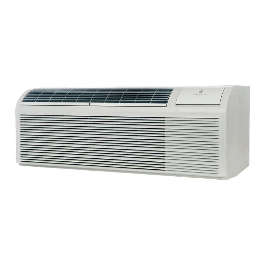
- Page 1 INSTALLATION & OPERATION GUIDE PTAC PACKAGED TERMINAL AIR CON DI TION ERS & HEAT PUMPS Standard Control Remote Thermostat Seacoast Protected 920-087-04 (8-05)
-
Page 2: Table Of Contents
920-087-04 (8-05) Table of Contents Unit Components .......................................2 Model Number Code ......................................3 Installation Recommendations ..................................4 Friedrich Digital Control Features ................................. 5-6 Drain Kit Installation ......................................7-8 Wall Sleeve Installation ....................................9-10 Deep Wall Installation ...................................... 11 Standard Grille Installation ....................................12 Electrical Rating Tables ....................................13 Power Cord Information .................................... -
Page 3: Model Number Code
920-087-04 (8-05) Thank you for your decision to purchase the newly designed Friedrich Packaged Terminal Air Conditioner (PTAC). We are confi dent that you will fi nd this unit a quiet and effi cient example of Friedrich reliability. This Installation and Operation Manual has been designed to insure maximum satisfaction in the performance of your unit. -
Page 4: Installation Recommendations
920-087-04 (8-05) PTAC Installation Recommendations For proper PTAC unit performance and maximum operating life please refer to the minimum installation clearances below: Figure 1 PTAC units should be installed no closer than 12" apart when THREE OR MORE PTACs two units are side by side. If ADJACENT 36"... -
Page 5: Friedrich Digital Control Features
Limiting of one another. When the PTAC senses that the indoor room temperature has fallen to 40°F the unit will cycle on high fan and the electric strip heat Room Freeze to raise the room temperature to 46°F then cycle off again. This feature works regardless of the mode selected and can be turned off. - Page 6 High effi ciency rotary compressors are used on all Friedrich PTACs to maximize durability and effi ciency. The Friedrich PTAC features a 24V AC terminal for connection to an auxiliary fan that may be used to transfer air to adjoining Auxiliary Fan Ready rooms.
- Page 7 920-087-04 (8-05) Installation Instructions PXDR10 Drain Kit NOTE: Determine whether drain will be located within the wall, on the indoor side, or will drain to the exterior of the build ing. Follow appropriate instructions below depending on your particular type of installation. Internal Drain (optional for new construction) NOTE: If installing an internal drain, you MUST install a drain kit on the wall sleeve before the wall sleeve is installed.
-
Page 8: Drain Kit Installation
920-087-04 (8-05) External Drain (for new construction or unit re place ment) When using an external drain system, the condensate is removed through either of two drain holes on the back of the wall sleeve. Select the drain hole which best meets your drainage situation and install the drain kit. Seal off the other with a cover plate. Drain Tube Installation Cover Plate Installation Peel the backing tape off the gaskets and apply the... -
Page 9: Wall Sleeve Installation
920-087-04 (8-05) Wall Sleeve Installation Instructions (PDXWS) NOTE: Insure that the unit is only installed in a wall structurally adequate to support the unit including the sleeve, chassis and accessories. If the sleeve projects more than 8" into the room, a sub base or other means of support MUST be used. Please read these instructions com plete ly before attempting in stal la tion. - Page 10 920-087-04 (8-05) Figure 6 Dimensions Dimension* Allow Allow for fl oor fi nishing ¼" for wall (6.4 cm) min. fi nishing (Minimum) Min. No Accessories ¼" ¼" (6.4 mm)* (6.4 mm) With Subbase 1¾" 3½" 5" (4.5 cm) (8.9cm) (12.7cm) 13¾...
-
Page 11: Deep Wall Installation
Installation Instructions for the PXWE – 4" Wall NOTE: Improper fabrication or installation of a wall sleeve Sleeve Extension extension will impair PTAC performance. The following points MUST be considered when installing a wall Extension Installation sleeve extension:... -
Page 12: Standard Grille Installation
920-087-04 (8-05) Installation Instructions Model PXGA Standard Grille 1. Remove the center support and weatherboard if still in stalled 5. Grasp the grille by the attached plastic handles. Po si tion in the sleeve. it with the con den sate drain knock outs facing down. From in side the build ing, ma neu ver the grille through the wall 2. -
Page 13: Electrical Rating Tables
NOTE: Use copper conductors only. B. Power Cord Information (230/208V models only) All Friedrich 230/208V PTAC units are shipped from the factory with NOTE: The LCDI device is not intended to be used as a switch. a Leakage Current Detection Interrupter (LCDI) equipped power Once plugged in the unit will operate normally without the need to cord. -
Page 14: Installation Checklist
2. Remove the front cover contained in a protective plastic bag from chassis. Remove the bag and dispose of it properly. IMPORTANT: When installing a Friedrich P-Series PTAC into an If the control door is not installed, follow these steps: existing sleeve, it is important to ensure that the unit is installed •... - Page 15 If the unit has been placed such that there is no the sleeve fl ange. room to insert the thumbscrews from the bottom, request a Side Mounting kit (Part No. PXSM) from Friedrich. Locate the service cord or conduit in the notch at the bottom right of the front cover.
-
Page 16: Digital Control User Input Confi Guration
Digital Control User Input Confi guration The adjustable control dip switches are located at the lower left hand portion of the digital Smart Center. The inputs are only visible and accessible with the front cover removed from the PTAC. Heating Range Switches 1 & 2 Dip Switch Setting 1) Electronic Temperature Limiting –... -
Page 17: Operation
Temperature Display Figure 12 Digital Control Panel The Friedrich digital PTAC is shipped from the factory to display the desired room temperature on the LED readout. The unit can be confi gured to display the room temperature by simultaneously pressing the ‘Cool’ and ‘High Fan’ buttons for three seconds the display will show an ‘R’... -
Page 18: Remote Thermostat And Low Voltage Control Connections
Remote Thermostat and Low Voltage Control Connections Remote Thermostat All Friedrich PD model PTAC units are factory confi gured to be Note: To revert back to the Smart Center control of the unit replace controlled by either the chassis mounted Smart Center or a 24V the jumper wire between the ‘GL’... -
Page 19: Desk Control Terminals
To connect the relay, simply wire one side of the relay to F1 and For desk control operation connect one side of the switch to the the other side to F2. Anytime that the PTAC fan runs the terminals D1 terminal and the other to the D2 terminal (See fi gure 13). -
Page 20: Start-Up Checklist
Installation Manual, all accessory installation instructions and the name, address and telephone Strictly follow installation instructions concerning number of the Authorized Friedrich Warranty clearances around the unit. Service Company in the area for the owner or operator. -
Page 21: Appendix A: Electrical Wiring For 265 V Models
920-087-04 (8-05) Appendix A: Electrical Wiring for 265 Volt Models NOTE: It is recommended that the PXSB subbase assembly, the PXCJ conduit kit and the PXDS disconnect switch be installed on all hardwired units. If installing a fl ush-fl oor mounted unit, make provisions for all the line voltage power leads and conduit to be removed for ease of maintenance and service to the chassis. -
Page 22: Routine Maintenance
920-087-04 (8-05) J. Routine Maintenance NOTE: Units are to be inspected and ser viced by qual i fi ed service per son nel only. 1. Clean the unit air intake fi lter at least every 300 to 350 hours 3. Periodically (at least yearly or bi-yearly): inspect all control of operation. -
Page 23: Basic Troubleshooting Techniques
Friedrich recommends that you consult with sizing of the unit. Friedrich recommends that you consult with an applications engineer for proper sizing. -
Page 24: Digital Control Diagnostics And Test Mode
For service and diagnostic use only, the built-in timers and operation and will store service codes if certain conditions are delays on the PTAC may be bypassed by pressing the ‘Cool’ witnessed. In some cases the unit may take action and shut the and ‘Low Fan’... -
Page 25: Accessories
920-087-04 (8-05) Friedrich PTAC Accessories NEW CONSTRUCTION AC CES SO RIES MODEL NUMBER DESCRIPTION PHOTO WALL SLEEVE zinc coated steel is prepared in an eleven-step process, then powder coated with a polyester fi nish and cured PDXWS in an oven for exceptional durability. The wall sleeve is insulated for sound absorption and thermal effi... -
Page 26: Accessories
DESIGNATOR DE SCRIP TION STANDARD UNIT Standard PTAC/PTHP chassis. Can be 230/208V or 265V, electric or heat pump. SEACOAST PROTECTION Additional protection for PTAC/PTHP units in a coastal or corrosive environment. The entire outdoor coil is submerged in a specially formulated enamel coating, then oven-... -
Page 27: Warranty
For international warranty information, contact the Friedrich Air Conditioning Company - International Division. Reasonable proof must be presented to establish the original purchase date, otherwise the beginning date of this certificate will be considered to be our shipment date plus sixty days. - Page 28 Friedrich Air Conditioning Co. Post Office Box 1540 • San Antonio, Texas 78295-1540 4200 N. Pan Am Expressway • San Antonio, Texas 78218-5212 (210) 357-4400 • FAX (210) 357-4480 www.friedrich.com Printed in the U.S.A. 920-087-04 (8-05)