Table of Contents
Advertisement
Safety Instructions
& Operator's Manual for
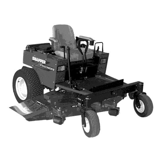
MID MOUNT Z-RIDER
ZERO TURNING
HYDRO DRIVE
SERIES 0
I POWER
UNIT MODELS
ZMT2500KH
I MOWER
UNIT MODELS
ZM5201M
I
ZM6101M
MODEL
NUMBER
EXPLANATION
DRIVE DESIGNATION
MOWER OPERATION
CONTROL DESIGNATION
Z - Zero Turnina -Hvdro
Drive
M - Mid Mount Mower
T-
Twin Control Levers
I ZIMIT
1__ 1 O0IKH I
I
I
POWER UNIT
26 - Enaine Horse Power
00 - Series Desianation
ENGINE TYPE
SERIES DESIGNATION
ENGINE HP
KH - Kohler Enaine
Z - Zero Turnina -Hvdro
Drive
M - Mid Mount Mower
MOWER UNIT
52 - Mower
Cuttina
Width
01 - Series
Desianation
61 - Mower Cutting Width
M - Mower
Deck
Thank you for buying a SNAPPER Product!
Before operating your machine, read this manual carefully and pay
particular attention to the "IMPORTANT
SAFETY INSTRUCTIONS"
on Pages 2 - 4.
Remember that all power
equipment
can be dangerous
if used improperly.
Also keep in mind that SAFETY requires careful use in
accordance with the operating instructions and common sense!
COPYRIGHT
© 2000
SNAPPER
INC.
ALL RIGHTS RESERVED
SNAPPER, McDonough,
GA.. 30253
U.S.A.
MANUAL No. 7-3704 (I.R. 5/16/00)
Advertisement
Table of Contents
Troubleshooting

Related Manuals for Snapper ZMT2500KH SERIES 0


Summary of Contents for Snapper ZMT2500KH SERIES 0
- Page 1 M - Mower Deck M - Mid Mount Mower 61 - Mower Cutting Width Thank you for buying a SNAPPER Product! Before operating your machine, read this manual carefully and pay particular attention to the "IMPORTANT SAFETY INSTRUCTIONS" on Pages 2 - 4.
-
Page 2: Important Safety Instructions
If you have any questions pertaining to your machine which your dealer cannot answer to your satisfaction, call or write the Customer Service Department at SNAPPER, McDonough, Georgia 30253. Phone: (1-800-935-2967). PROTECTION... - Page 3 Only accessories attachments approved by SNAPPER. 10. Slow down before turning. Keep people pets mowing area. 11. Watch out for traffic when...
- Page 4 15. Have machine serviced authorized SNAPPER dealer at least once a year and have the dealer install any new safety devices. Never allow untrained personnel to service machine. 16. Use only genuine SNAPPER replacement parts assure...
-
Page 5: Table Of Contents
Operator Protective Structures may be required by local ordinances. Discuss your mowing application and ordinances with your local Snapper Dealer. -
Page 6: Section 1 - Familiarization
This manual has been prepared for the operator's of the The nomenclature information above, Figure 1.1, shows the essential parts of the SNAPPER MID MOUNT Z- SNAPPER MID MOUNT Z-RIDER. Its purpose, aside from RIDER. It is recommended that all operator's of this recommending standard operating procedures and routine... -
Page 7: Section 2 - Safety Messages And Symbols
Section 2 - SAFETY MESSAGES AND SYMBOLS CHOKE RABBIT "ON" "FAST" CHOKE ENGINE SPEED... - Page 8 Section 2 - SAFETY MESSAGES AND SYMBOLS BLADES ENGAGED "ON" BLADES DISENGAGED "OFF" READ OPERATOR'S MANUAL BEFORE MOTION CONTROL OPERATING MACHINE MULTIDIRECTIONAL KEEP CHILDREN AND OTHERS OUT OF MOWING DANGER! ROTATING BLADES AREA DANGER! ROTATING BLADES...
-
Page 9: Section 2 - Safety Messages And Symbols
Section 2 - SAFETY MESSAGES AND SYMBOLS MOVE MOTION CONTROLS GENTLY WITH CAUTION DESIRED DIRECTION: FORWARD- Move both controls forward. REVERSE- Move both controls to the rear. LEFT TURN- Move left control towards neutral position. RIGHT TURN- Move right control towards neutral position. ZERO RADIUS TURN- Move one control forward of neutral and one... -
Page 10: Operating Instructions
Section 3 -OPERATING INSTRUCTIONS PRE-START CHECK LIST 2.1.8. Place mower in desired cutting height Make the following checks and perform the service setting. Grasp deck lift lever and depress release required before each start-up. button located at tip of lever. Move lever to desired 2.1.1. -
Page 11: Starting & Stopping Engine, Blades & Parking Brake
POSITION necessary. Return the machine to an authorized Snapper dealer for replacement. DO NOT CONTINUE to operate mower if blades fail to stop in 7 seconds. 2. Move engine speed control to the Turtle "SLOW" position. Turn key to "STOP"... -
Page 12: Parking Brake
Section 3 -OPERATING INSTRUCTIONS 2.2.5. PARKING BRAKE 1. Engage parking brake by pulling the parking DO NOT park the machine on slopes. DO NOT I brake lever back to the engaged position. NOTE: Motion control levers must be in the machine with engine running. -
Page 13: 2.3 Cutting Height Adjustment
Section 3 -OPERATING INSTRUCTIONS 2.3 CUTTING HEIGHT ADJUSTMENT WARNING Adjust cutting height as desired to any position, DO NOT make turns at high speed. Slow machine using deck lift lever. See Figure 2.8. motion. Move motion control levers gently and with NOTE: The engine does not have to be running to adjust caution. -
Page 14: Maintenance Instructions
3.1 INTRODUCTION Fill engine crankcase with new oil. Refer to To retain the quality of the SNAPPER mower, use your engine owner's manual for oil specifications. genuine SNAPPER replacement parts only. Contact a Change oil filter at every oil change. -
Page 15: Check Mower Drive Belt
Section 4 - MAINTENANCE 3.2.3. CHECK MOWER DRIVE BELT Raise mower deck to its highest setting. It may be 1. Foot Rest Removal necessary to raise mower deck higher using a hydraulic floor jack. Secure machine with safety blocks. Lower deck to lowest setting. Clean underside of mower deck, removing b. -
Page 16: Front Wheel Bearings Lubrication
DO NOT remove or service the transaxle fluid filters. This service should be made periodically by an 3.4 BEFORE OPERATING MACHINE authorized SNAPPER dealer. service Clean all dirt and debris from around the two schedule to determine the recommended change hydraulic fluid reservoirs. -
Page 17: Fuel Filter Replacement
Section 4 - MAINTENANCE ANNUALLY (END OF EACH SEASON) POSITION DECK (Continued from previous Page) LIFT LEVER IN 3.5.2. FUEL FILTER HIGHEST CUTTING Service fuel filter as instructed below. Turn key to POSITION, PLACE WOODEN BLOCKS "OFF" position. Engine MUST be stopped UNDER FRONT &... -
Page 18: Power Transfer Shaft Removal
Section 4 - MAINTENANCE 3.6 DECK REMOVAL (Continued from previous page) TRANSFER Remove shoulder bolts, washers and nuts from rear SHAFT lift arm. See Figure 3.10. PULL LOCK COLLAR BACK & SLIDE TRANSFER REAR SHAFT AWAY COLLAR LIFT ARM FROM TAKE OFF SHAFT I II TAKE... -
Page 19: Neutral Position Adjustments
SNAPPER dealer. NEUTRAL POSITION ADJUSTMENTS 4.2.1. MOWER DECK ADJUSTMENT (LEVELNESS) The motion control levers control the movement SIDE to SIDE and FRONT to REAR stopping of the machine. -
Page 20: Mower Deck Adjustment (Levelness)
Section 5- ADJUSTMENTS & REPAIR 11. Place a wooden block under the front and rear 4.2.1. MOWER DECK ADJUSTMENT (LEVELNESS) (Continued) edge of the mower deck. Loosen the nuts and bolts that secure both front 12. Move deck lift lever and set the mower deck to a and rear deck support brackets on the high side of lower cutting position until deck rests on wooden deck. -
Page 21: Parking Brake Adjustment
18 to 22 pounds of force to set the brake. If this adjustment does not result in proper braking action contact your authorized SNAPPER dealer for corrective action. See Figure 4.3. Do not operate this machine... -
Page 22: Mower Blade Sharpening
Section 5- ADJUSTMENTS & REPAIR MOWER DRIVE BELT REPLACEMENT 4.5.2. BLADE SHARPENING Inspect mower drive belt. Replace belt if it shows signs Remove blade. See Figure 4.5. of excessive wear, damage and/or is broken. 4.6.1. BELT REMOVAL Remove power unit foot rest. BLADE Remove old belt. -
Page 23: Battery Removal
Section 5- ADJUSTMENTS & REPAIR With cell caps removed, connect battery charger WARNING to battery terminals. RED to positive (+) terminal and Shield positive terminal with terminal cover BLACK to negative (-) terminal. located on battery harness. This prevents metal from Slow charge battery at 1 amp for 10 hours. -
Page 24: Battery Testing
Section 5- ADJUSTMENTS & REPAIR Battery Condition Chart State of Charge Syringe Hydrometer Digital Voltmeter Five Ball Hydrometer 1.280 12.80v 100% Charged w/Sulfate Stop Five Balls Floating 1.265 12.60v 100% Charged Four Balls Floating 1.210 12.40v 75% Charged Three Balls Floating 1.160 12.10v 50% Charged... -
Page 25: Troubleshooting
Blown fuse. Engine 2. Replace fuse. Electrical connections loose or corroded• 3. Clean and check connections for good contact• Contact authorized SNAPPER dealer• Defective ignition switch• Engine Will Not Start • Blade engagement switch in the "ON" position• • Move blade engagement switch to "OFF". -
Page 26: Troubleshooting
9. Adjust to proper specifications• 10. Check clutch belt. 10. Replace clutch belt. 11. Check gearbox for damage• 11. Contact authorized SNAPPER dealer• Poor Grass Discharge 1. Engine speed too slow. 1. Move throttle control to "FAST" position• 2. Forward speed too fast. -
Page 27: Service Schedule
SERVICE SCHEDULE ITEM SERVICE PERFORMED REF. EACH EACH SEASON Check Oil Level Page 10 Engine Oil Initial Oil Change Page 14 Periodic Oil Change Page 15 Air Pre-Cleaner Clean Sponge Element Engine Manual & Page 15. Air Cleaner Clean or Replace Engine Manual. -
Page 28: Warranty
SNAPPER, through any authorized SNAPPER dealer will replace, free of charge (except for taxes where applicable), any part or parts found upon examination by the factory at McDonough, Georgia, to be defective in material or workmanship or both. SNAPPER FIELD SERy_CEABLE SPINDLES and their components used on SNAPPER PRO ®... - Page 29 & how reasonable maintenance can protect it! Snapper uses the best avail- able engines and components in their products in order to provide long, satisfactory service. However, proper care is essential In prolonging engine life. Dirt...
-
Page 30: Primary Maintenance
Because of its working environ- ment, the air available to your Snapper engine Is " heavily saturated with air- borne dirt particles. As the dirt particles are stopped, Damage caused by a poorly serviced air... - Page 31 PRIMARY MAINTENANCE Air is also needed to keep your engine cool. Dirt, dust & debris build up to restrict and clog cooling air Intake screens and fins. Clean screens and fins at frequent Intervals. The engine blower housing and shrouds should be removed at least once each season or more often t under dry, dusty conditions...
- Page 32 2-cycle engine fuel, be sure the containers are clearly marked to avoid mix-up. Snapper 2-cycle engines require a 32 to 1 mixture of gasollna and BIA certified TC-W oll such as Snapper's 2-cycle engine o11. Many of the 2-cycle engine oils on the...
- Page 33 NOTES...
- Page 34 NOTES...
- Page 35 NOTES...
-
Page 36: Important
ZMT2500KH MOWER UNIT MODELS ZM5201M I ZM6101M IMPORTANT Snapper products are built using engines that meet or exceed all applicable emissions requirements on the date manufactured. The labels on those engines contain very important emissions information and critical safety warnings.
Need help?
Do you have a question about the ZMT2500KH SERIES 0 and is the answer not in the manual?
Questions and answers