Snapper 1 Series Operator's Manual

Hide thumbs Also See for 1 Series:

Advertisement

Quick Links

DRIVE SYSTEM TYPE
MOWER ORIENTATION
Z – Zero Turning – Hydro Drive
M – Mid Mount Mower
Z – Zero Turning – Hydro Drive
M – Mid Mount Mower
Thank you for buying a SNAPPER Product! Before operating your machine, read this manual carefully and pay
particular attention to the "IMPORTANT SAFETY INSTRUCTIONS" on Pages 2 & 3. Remember that all power
equipment can be dangerous if used improperly. Also keep in mind that SAFETY requires careful use in
accordance with the operating instructions and common sense!
COPYRIGHT © 1999
SNAPPER INC.
ALL RIGHTS RESERVED
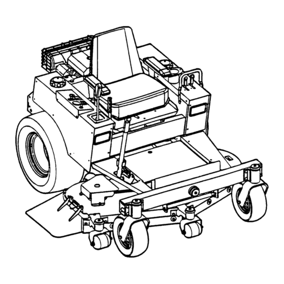
Safety Instructions & Operator's Manual for
MODEL NUMBER EXPLANATION
Z
M
25 – Engine Horse Power
52 – Mower Cutting Width
61 – Mower Cutting Width
MID MOUNT Z-RIDER
ZERO TURNING
HYDRO DRIVE
25
01
KH
POWER UNIT
01 – Series Designation
MOWER UNIT
00 – Series Designation
SERIES 1
POWER UNIT MODELS
ZM2501KH
MOWER UNIT MODELS
ZM5200M
SERIES DESIGNATION
KH – Kohler Engine
M – Mower Deck
MANUAL No. 7-2902 (REV. 1, 8/20/99)
ZM6100M
ENGINE TYPE
ENGINE HP

Advertisement

Table of Contents
loading

Summary of Contents for Snapper 1 Series

  • Page 1 M – Mid Mount Mower 61 – Mower Cutting Width Thank you for buying a SNAPPER Product! Before operating your machine, read this manual carefully and pay particular attention to the “IMPORTANT SAFETY INSTRUCTIONS” on Pages 2 & 3. Remember that all power equipment can be dangerous if used improperly.
  • Page 2: Section 1 - Important Safety Instructions

    If you have any questions pertaining to your machine which your dealer cannot answer to your satisfaction, call or write the Customer Service Department at SNAPPER, McDonough, Georgia 30253. Phone: (1-800-935-2967).
  • Page 3 14. Have machine serviced by an authorized SNAPPER 9. Slow down before turning. dealer at least once a year and have the dealer 10. Watch out for traffic when near or crossing install any new safety devices.
  • Page 4: Table Of Contents

    These structures, when installed and used properly can offer additional security to the operator against serious injury in the event of a tip over accident. Operator Protective Structures may be required by local ordinances. Discuss your mowing application and ordinances with your local Snapper Dealer.
  • Page 5: Section 1 - Familiarization

    1.2 NOMENCLATURE The nomenclature information above, Figure 1.1, shows This manual has been prepared for the operator’s of the the essential parts of the SNAPPER MID MOUNT Z- SNAPPER MID MOUNT Z-RIDER. Its purpose, aside RIDER. It is recommended that all operator’s of this...
  • Page 6: Section 2 - Operating Instructions

    Section 2 - OPERATING INSTRUCTIONS 2.1 PRE-START CHECK LIST IMPORTANT: This machine equipped with Make the following checks and perform the service hydrostatic drive. The forward and rearward movement required before each start-up. of the mower is controlled by a joystick lever. Joystick 2.1.1.
  • Page 7: Starting & Stopping Engine, Blades & Parking Brake

    Section 2 - OPERATING INSTRUCTIONS 2.2 STARTING & STOPPING – ENGINE, BLADES, PARKING BRAKE “STOP” This machine is equipped with dual hydrostatic POSITION wheel drive transmissions. Each transmission is controlled by a single motion control lever or joystick. This single control lever (joystick) controls the direction of motion, Forward and Reverse, and the speed of motion.
  • Page 8: Parking Brake

    Section 2 - OPERATING INSTRUCTIONS 2.2.5. PARKING BRAKE WARNING 1. Engage parking brake by pulling the parking DO NOT park the machine on slopes. DO NOT leave brake lever back to the engaged position. machine with engine running. Stop engine. Stop NOTE: Motion control lever must be in the Neutral blades.
  • Page 9: Adjusting Cutting Height

    Section 2 - OPERATING INSTRUCTIONS 2.3 CUTTING HEIGHT ADJUSTMENT WARNING 1. Adjust cutting height as desired to any position, DO NOT make turns at high speed. Slow machine using deck lift lever. See Figure 2.8. motion. Move motion control lever gently and with NOTE: The engine does not have to be running to adjust caution.
  • Page 10: Section 3 - Maintenance Instructions

    Section 3 - MAINTENANCE 3.1 INTRODUCTION d. Fill engine crankcase with new oil. To retain the quality of the SNAPPER mower, use Refer to your engine owner’s manual for genuine SNAPPER replacement parts only. Contact a oil specifications. local SNAPPER dealer for parts and service assistance.
  • Page 11: Check Mower Drive Belt

    Section 3 - MAINTENANCE 3.2.3. CHECK MOWER DRIVE BELT 1. Foot Rest Removal c. Raise mower deck to its highest setting. It may be necessary to raise mower deck a. Lower deck to lowest setting. higher using a hydraulic floor jack. Secure b.
  • Page 12: Front Wheel Bearings Lubrication

    Especially around the top be made periodically by an authorized and cap area. SNAPPER dealer. See the service schedule 2. Clean all dirt and debris from the cooling fins on to determine the recommended change the engine and from both hydraulic pumps.
  • Page 13: Fuel Filter Replacement

    Section 3 - MAINTENANCE 3.5 ANNUALLY (END OF EACH SEASON) (Continued from previous Page) 3.5.2. FUEL FILTER POSITION DECK Service fuel filter as instructed below. Turn key to LIFT LEVER IN “OFF” position. Engine MUST be stopped and MUST HIGHEST be cold before removing filter.
  • Page 14: Power Transfer Shaft Removal

    Section 3 - MAINTENANCE 3.6 DECK REMOVAL (Continued from previous page) TRANSFER SHAFT 5. Remove shoulder bolts, washers and nuts from rear lift arm. See Figure 3.11. LOCK REAR COLLAR LIFT ARM TAKE OFF SHAFT REAR LINK SHOULDER PLATE BOLT, WASHER &...
  • Page 15: Section 4 - Adjustments And Repair

    However, if there is difficulty in making these adjustments and repairs, it is recommended that these repairs be made by an authorized SNAPPER 4.1 NEUTRAL POSITION ADJUSTMENTS dealer. The joystick controls the movement and stopping of 4.2.1.
  • Page 16 Section 4 - ADJUSTMENTS & REPAIR 10.Move deck lift lever and set the mower deck 4.2.1. MOWER DECK ADJUSTMENT (LEVELNESS) to the highest cutting position. (Continued) 11.Place a wooden block under the front and 6. Loosen the nuts and bolts that secure both rear edge of the mower deck.
  • Page 17: Parking Brake Adjustment

    If this adjustment 4.5.1. BLADE WEAR LIMITS does not result in proper braking action contact your 1. Inspect blade frequently for signs of authorized SNAPPER dealer for corrective action. excessive wear or damage. See Figure 4.4. See Figure 4.3. WARNING...
  • Page 18: Mower Drive Belt Removal & Replacement

    Section 4 - ADJUSTMENTS & REPAIR 4.6 MOWER DRIVE BELT REPLACEMENT 4.5.2. BLADE SHARPENING Inspect mower drive belt. Replace belt if it shows 1. Remove blade. See Figure 4.5. signs of excessive wear, damage and/or is broken. 4.6.1. BELT REMOVAL 1.
  • Page 19: Battery Removal

    Section 4 - ADJUSTMENTS & REPAIR 4. With cell caps removed, connect battery WARNING charger to battery terminals. RED to positive Shield the positive terminal with terminal cover (+) terminal and BLACK to negative (-) located on battery harness. This prevents metal from terminal.
  • Page 20: Battery Testing

    Section 4 - ADJUSTMENTS & REPAIR Battery Condition Chart State of Charge Syringe Hydrometer Digital Voltmeter Five Ball Hydrometer 100% Charged w/ Sulfate Stop 1.280 12.80v Five Balls Floating 100% Charged 1.265 12.60v Four Balls Floating 75% Charged 1.210 12.40v Three Balls Floating 50% Charged 1.160...
  • Page 21: Troubleshooting

    3. Electrical connections loose or corroded. 3. Clean and check connections for good contact. 4. Defective ignition switch. 4. Contact authorized SNAPPER dealer. 1. Blade engagement switch in the “ON” position. 1. Move blade engagement switch to “OFF”. Engine Will Not Start 2.
  • Page 22 2. Replace clutch belt. 3. Mower belt slipping. 3. Replace mower belt. 4. Electric clutch not functioning. 4. Contact authorized SNAPPER dealer. 5. Check gearbox for damage. 5. Contact authorized SNAPPER dealer. 6. Power transfer shaft disconnected or damaged. 6. Connect power transfer shaft or repair damage.
  • Page 23: Service Schedule

    SERVICE SCHEDULE ITEM SERVICE PERFORMED REF. EACH EACH SEASON Engine Oil Check Oil Level Page 6 Initial Oil Change Page 10 Periodic Oil Change Page 11 Clean Sponge Element Engine Manual Air Pre-Cleaner & Page 11. Clean or Replace Engine Manual. Air Cleaner Replace Engine Manual.
  • Page 24: Warranty

    For two (2) years from purchase date for the original purchaser's use, SNAPPER, through any authorized SNAPPER dealer will replace, free of charge (except for taxes where applicable), any part or parts found upon examination by the factory at McDonough, Georgia, to be defective in material or workmanship or both.
  • Page 25: Primary Maintenance

    PRIMARY MAINTENANCE...
  • Page 26 PRIMARY MAINTENANCE...
  • Page 27 PRIMARY MAINTENANCE...
  • Page 28 PRIMARY MAINTENANCE...
  • Page 29 NOTES...
  • Page 30 NOTES...
  • Page 31 NOTES...
  • Page 32: Important

    Read, Understand, and Follow all warnings and instructions in this manual, the engine manual, and on the machine, engine and attachments. If you have any questions about your Snapper product, contact your local authorized Snapper dealer or contact Snapper Customer Service at Snapper, McDonough, GA.

This manual is also suitable for:

Zm2501khZm5200mZm6100m

Table of Contents