
Related Manuals for La Crosse WS-9096U


Summary of Contents for La Crosse WS-9096U
- Page 1 WS-9096U Wireless 433 MHz Radio-controlled Sun/Moon Weather Station Instruction Manual...
-
Page 2: Table Of Contents
Topic Page Inventory of Contents/Additional Equipment About WWVB Quick Set-Up Guide Detailed Set-Up Guide Battery Installation Program Mode Function Keys LCD Screen Manual Settings Sequence LCD Contrast Setting City Location Setting Time Zone Setting Daylight Saving Time (DST) Setting WWVB On/Off Setting 12/24 Hour Setting Manual Time Setting Calendar Setting... -
Page 3: Inventory Of Contents/Additional Equipment
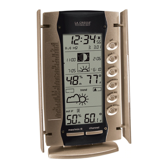
INVENTORY OF CONTENTS 1. The indoor weather station (Figure 1). 2. One TX7U remote temperature/humidity sensor with mounting bracket (Figure 2). 3. Three each, ½” Philips screws. 4. One strip double-sided adhesive tape. 5. Instruction manual and warranty card. Time LCD Sun/moon Hanging hole Indoor LCD... -
Page 4: About Wwvb
ABOUT WWVB (Radio Controlled Time) The NIST (National Institute of Standards and Technology—Time and Frequency Division) WWVB radio station is located in Ft. Collins, Colorado and transmits the exact time signal continuously throughout the United States at 60 kHz. The signal can be received up to 2, 000 miles away through the internal antenna in the weather station. -
Page 5: Quick Set-Up Guide
QUICK SET-UP GUIDE Hint: Use good quality Alkaline Batteries and avoid rechargeable batteries. 1. Have the indoor weather station and remote temperature/humidity sensor 3 to 5 feet apart. 2. Batteries should be out of both units for 10 minutes. 3. Place the batteries into the remote temperature/humidity sensor first then into the indoor weather station. -
Page 6: Detailed Set-Up Guide
DETAILED SET-UP GUIDE I. Battery Installation A. Remote Temperature/Humidity Sensor 1. Remove the battery Battery cover. compartment Battery cover 2. Observing the correct polarity install 2 AA batteries. The batteries will fit tightly (to avoid start-up problems make sure they do not spring free). -
Page 7: Program Mode
II. Program Mode Programming Note: If 30 seconds are allowed to pass or either the IN or the OUT button is pressed during programming modes, the unit will set the last information entered—the display will stop flashing and return to normal time-date readings. A. - Page 8 3. MINUS (-) button • Decrease value in all setting modes • Decrease the digits • Stop the alarm during alarm ringing 4. SUN/MOON button • Enter the sun/moon setting mode • Start the sun/moon time calculation of the selected city •...
-
Page 9: Lcd Screen
B. LCD Screen The LCD screen is split into 5 sections displaying the information for time and date, sun/moon data, indoor data, weather forecast and outdoor data. Time reception icon Time (for WWVB time) Date display Alarm icon City location light Moon icon/Moon phases icon Moonrise time... - Page 10 LCD Contrast Setting Last digit flashing The LCD contrast can be set within 8 levels, from LCD 0 to LCD7 (the default setting is LCD 5): 1. Press and hold the “SET” button until the digit starts flashing in the LCD. 2.
- Page 11 Time Zone Setting Flashing The default (factory set) time zone of the indoor weather station is EST –5 (the default time zone for the default city, Washington D.C.). To set a different time zone: 1. The current time zone value starts flashing on the LCD. 2.
- Page 12 WWVB ON/OFF Setting Digits flashing Tower icon flashing In areas where reception of the WWVB time is not possible the WWVB time reception function can be turned OFF. The clock will then work as a normal Quartz clock. (the default setting is ON). 1.
- Page 13 Manual Time Setting In case the indoor weather station cannot detect the WWVB signal (for example due to disturbances, transmitting distance, etc.), the time can be manually set. The clock will then work as a normal Quartz clock. Minutes flashing Hour flashing 1.
- Page 14 Calendar Setting Date Month Year (For 24H Display) Month Date Year (For 12H Display) The default (factory set) date of the indoor weather station is 1. 1. in the year 2001. Once the radio-controlled time signal is received the date is automatically updated. If the signals are not received the date can also be set manually.
- Page 15 Snooze Setting Snooze time The snooze time can be set from OFF to a maximum time of 30 minutes. The default (factory) setting is OFF. 1. The digits “OFF” will start flashing in the LCD. 2. Press and release the PLUS (+) or MINUS (-) button to set the snooze time. Each pressing of the button will increase or decrease the snooze time by 5 minutes.
-
Page 16: Weather Forecast Icon Sensitivity Setting
To exit the manual setting mode anytime during the manual setting modes, press the “CHANNEL” button anytime or wait for automatic timeout. The mode will return to the normal time display. III. FEATURES OF THE WS-9096U Alarm Setting Digits flashing Alarm icon The alarm time can be set by pressing the “ALARM SET”... - Page 17 6. Press and release the PLUS (+) or MINUS (-) button to set the alarm minute. 7. Press and release the “SET” button to confirm and exit the Alarm setting. Note: The maximum alarm ring duration is 3 minutes. The alarm setting can be activated or deactivated by pressing the “ALARM ON/OFF”...
-
Page 18: Moon Phase Symbols
Note: It will take a few seconds until the sun/moon data will be displayed. The display will return after 3 minutes to normal mode. The “CH” button can also be used to return immediately to the normal display mode. If only a specific data is changed, e.g. -
Page 19: Weather Forecast And Tendency
WEATHER FORECAST AND WEATHER TENDENCY: WEATHER FORECASTING ICONS: Note: The weather forecast icons of this indoor weather station are a prediction of what the weather is going to do in the next 12 to 20 hours. These are not indications of the current weather. Weather icons in the fourth section of LCD can be displayed in any of the following combinations: Sunny... -
Page 20: Outdoor Temperature And Humidity
Common to weather forecasting, absolute accuracy cannot be guaranteed. The weather forecasting feature is estimated to have an accuracy level of about 75% due to the varying areas the indoor weather station has been designed for use in. In areas that experience sudden changes in weather (for example from sunny to rain), the indoor weather station will be more accurate compared to use in areas where the weather is stagnant most of the time (for example mostly sunny). - Page 21 ADDING OUTDOOR REMOTE TEMPERATURE SENSORS (OPTIONAL) The WS-9096U is able to receive signals from 3 different remote temperature sensors. The remote temperature sensor model(s) that you choose will come with their own set of instructions. Follow these instructions for a complete guide to setting up.
-
Page 22: Mounting
Note: When setting up multiple units it is important to remove the batteries from all existing units in operation. Then insert batteries into all the remote temperature sensor units in numeric sequence. Second, install batteries into the indoor weather station. Transmission problems will arise if this is not done correctly and if the total time for set-up exceeds 6 minutes. - Page 23 THE REMOTE TEMPERATURE/HUMIDITY SENSOR The remote temperature/humidity sensor is supplied with a holder that may be attached to a wall with the screws supplied. The remote temperature/humidity sensor can be mounted in three ways: • Mounting with screws • Mounting with adhesive tape •...
- Page 24 4. Screw mounting bracket onto the mounting surface. Ensure that the screws are flush with the bracket. 5. Insert the remote temperature/humidity sensor into the bracket. MOUNTING WITH ADHESIVE TAPE 1. With a nonabrasive solution, clean and dry the back of the mounting bracket and the mounting surface to ensure a secure hold.
-
Page 25: City List
B. WALL MOUNTING 1. Remove the table stand. To do this, pull down on the stand from the rear and rotate forward. 2. Fix a screw (not included) into the desired wall leaving approximately 3/16 of an inch (5mm) extended from the wall. -
Page 26: Troubleshooting
3) Be sure all batteries are fresh. Problem: Remote humidity displays “- -“ Solution: 1) A temperature only sensor is being used and displayed 2) The humidity is outside the range of 1-99% NOTE: For problems not solved, please contact La Crosse Technology. -
Page 27: Maintenance & Care
They may mark the displays and casings. • Do not submerge in water. • Immediately remove all low powered batteries to avoid leakage and damage. • Opening the casings invalidates the warranty. Do not try to repair the unit. Contact La Crosse Technology for repairs. -
Page 28: Specifications
SPECIFICATIONS Temperature measuring range: Indoor: 32°F to 140°F with 0.1°F resolution. (0°C to 60°C with 0.1°C resolution) “OF” displayed if outside this range Outdoor: -21.8°F to 157.8°F with 0.1°F resolution. (-29.9°C to 69.9°C with 0.1°C resolution) “OF” displayed if outside this range Indoor/Outdoor relative 1% to 99% with 1% resolution. -
Page 29: Warranty Information
La Crosse Technology, Ltd or La Crosse Technology, Ltd’s authorized service center. La Crosse Technology, Ltd will repair or replace this product, at our option and at no charge as stipulated herein, with new or reconditioned parts or products if found to be defective during the limited warranty period specified above. - Page 30 State. Some States do no allow the exclusion of consequential or incidental damages therefore the above exclusion of limitation may not apply to you. For warranty work, technical support, or information contact: La Crosse Technology 2809 Losey Blvd. S. La Crosse, WI 54601 Phone: 608.782.1610 Fax: 608.796.1020 e-mail: support@lacrossetechnology.com (warranty work) sales@lacrossetechnology.com...
Need help?
Do you have a question about the WS-9096U and is the answer not in the manual?
Questions and answers