
Subscribe to Our Youtube Channel
Related Manuals for SATO GY412


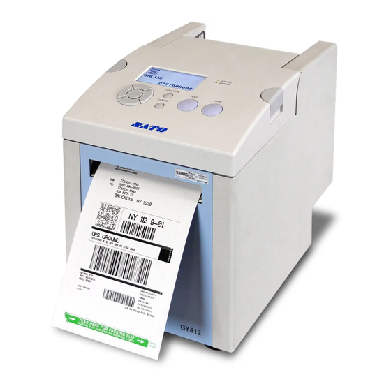
Summary of Contents for SATO GY412
- Page 1 Operator Manual For printer model: GY412 PN: 9001246(B) Read this manual before using this product. Keep this document available for future reference. www.satoamerica.com...
- Page 2 The content of this document may be changed without prior notice. Great care has been taken in the preparation of this document. If any problems, mistakes, or omissions are found, please contact your SATO reseller or technical support center. FCC Statement The printer complies with the requirements in Part 15 of FCC Rules for a Class B Computing Device.
-
Page 3: Safety Precautions
Do not place flower vases, cups, the power cord. Also, do not place your SATO reseller or technical or other containers holding liquids, heavy objects on the power cord, support center for repairs. It is... - Page 4 Doing so could result in electric You should not replace the print shock. head without having received the proper training. Page ii GY412 Operator Manual...
-
Page 5: Power Supply
Connect the power cord to a grounded power plugged into. This may cause voltage reduction and outlet. malfunction. Make sure that the printer is plugged into a grounded power outlet. Page iii GY412 Operator Manual... - Page 6 Safety Precautions Page iv GY412 Operator Manual...
-
Page 7: Table Of Contents
7.5 Local Area Network (LAN) Ethernet ................... 7-7 Appendix......................... 8-1 8.1 Cutter and Printer Motion ....................8-2 8.1 Cutter and Printer Motion (cont’d) ..................8-3 8.2 Offset Position Adjustment ....................8-7 8.3 Head Check Motion......................8-9 Page 1 GY412 Operator Manual... - Page 8 8.5 Head Position (Up and Down)..................8-12 8.6 Reverse Eject Motion ....................... 8-14 8.7 Segmented Printing......................8-15 8.8 Print Speed and Label Size....................8-17 8.9 Label Saving Function...................... 8-18 8.10 Print Operation Sequence ....................8-19 Page 2 GY412 Operator Manual...
-
Page 9: Introduction
1.1 FEATURES OF THE PRINTER The GY412 printer is a direct thermal printer that simultaneously prints on both sides of a label; the printer has two thermal print heads. The thermal label media is coated on each side using thermal technology. -
Page 10: Unpacking
4. Set the printer on a solid, flat surface. Inspect the shipping container and printer for any sign of damage that may have occurred during shipping. Please note that SATO shall hold no liability of any damage of any kind sustained during shipping of the product. -
Page 11: Parts Identification
Turns power on or off. Label discharge outlet “ | ” is on Discharges the printed “ ” is off. label. Upper print head Upper platen roller Label length detection sensor Feed roller Lower print head Lower platen roller Page 1-3 GY412 Operator Manual... - Page 12 Section 1: Introduction Back side of the printer Feed Roller Label feed Label guide lock entrance lever LAN interface Label guide USB interface RS-232C interface Left side of the printer SD card slot Page 1-4 GY412 Operator Manual...
- Page 13 Section 1: Introduction Right side of the printer AC input connector Connect the power cord to the printer here and plug its opposite end into the appropriate power receptacle. Page 1-5 GY412 Operator Manual...
-
Page 14: Operator Panel
Returns to the position after setting the label, previous screen. press the LINE button to go offline, and then, press the FEED button to automatically adjust the label position to its top of form position. Page 1-6 GY412 Operator Manual... -
Page 15: Installation
This section assists you in installing consumable media in the printer, as well as adjustment instructions, and installing other optional attachment units. The following information is provided: • 2.1 Site Location • 2.2 Media Selection • 2.3 Loading Labels • 2.4 Connections • 2.5 Turning Off/On LCD Backlight Page 2-1 GY412 Operator Manual... -
Page 16: Site Location
For optimal print performance and durability, please use SATO-certified label and supplies on this printer. Using supplies not tested and approved for use by SATO can result in unnecessary wear and damage to vital parts of the printer, and it may void the warranty. -
Page 17: Loading Labels
On the top surface of the printer, press down on one or both of the semi-circular blue buttons to open the top cover. Figure 2-5, Opening the top cover Note: • We recommend that you set the printer for either the I-mark sensor or the gap sensor before you load labels. Page 2-3 GY412 Operator Manual... - Page 18 The printer will automatically feed it. Depending on the sensor type to be used, when you turn on the power, the top of the label or I-mark will be detected and then, the printer will feed the label to the standby position. Figure 2-1, Inserting the media Page 2-4 GY412 Operator Manual...
-
Page 19: Connections
Settable Main Port RS-232C RS-232C Sub Port 2.4.4 Attaching Interface Cable This section explains the power cable and interface cable connection procedures. The GY412 interface types are: USB interface: USB B-type connector LAN interface (10/100 BASE) RS-232C interface Page 2-5... - Page 20 Section 2: Installation 2.4 CONNECTIONS, CONT’D Use one of the figures below to connect the cable for your interface to the printer. Figure 2-2, USB interface Figure 2-3, LAN interface Page 2-6 GY412 Operator Manual...
- Page 21 Section 2: Installation 2.4 CONNECTIONS, CONT’D RS-232C Figure 2-4, RS-232C interface In addition, there is an SD card slot (1 slot) * Eject type. Page 2-7 GY412 Operator Manual...
- Page 22 To remove the card from the printer, it is best to switch off the printer. Then, with your finger, press the card edge a slight amount to release the card from the slot. The slot will immediately release the card. Page 2-8 GY412 Operator Manual...
-
Page 23: Section 2: Installation
Download font data : USRFONTX.DAT (X : Reg. No. (1 to 6)) CONF Printer configuration information Printer configuration information file : PRN42.INI Rasterized font No corresponding files for GY412 Maintenance Receive buffer : RCVBUF.DAT STATUS5 log : HISTSTS5.DAT FRAM dump : FRAMDMP.DAT... - Page 24 When you save the data to the SD card by using the save-related commands, its file creation date will be the firmware release date. 2.4.6 Connecting the power cable and turning on power This section explains the power cable connection procedures. After installing the printer, connect the power cord as shown below. Page 2-10 GY412 Operator Manual...
- Page 25 A three-prong power cord is provided. If your power socket has three contacts, the third one is connected to the ground for safety. If your power outlet has two slots, use a three-prong to two-prong adapter. Press the power switch to the direction of [ | ]. Page 2-11 GY412 Operator Manual...
- Page 26 Ensure that the printer is in OFFLINE mode before you turn off the power. If the printer is in ONLINE mode, press the LINE button to go OFFLINE. After an [OFFLINE] message is displayed on the LCD screen, press the power switch toward [ o ]. Page 2-12 GY412 Operator Manual...
-
Page 27: Turning Off/On Lcd Backlight
Pressing any button while the LCD backlight is Off will turn the LCD backlight On. (If you press the LINE button in ONLINE Mode while the LCD backlight is Off, the printer does not go OFFLINE.) Page 2-13 GY412 Operator Manual... - Page 28 Section 2: Installation This page is intentionally left blank. Page 2-14 GY412 Operator Manual...
-
Page 29: Operation And Configuration
Before using the printer, it is best to read this manual thoroughly. Otherwise, you may disturb default settings on which the instructional procedures in this manual are based. Most of the printer’s settings are controlled via standard SBPL commands or by using the provided SATO Utilities Tool application. -
Page 30: Operator Panel
Green light blinks when detecting buffer near full. Power saving function (LCD backlight is OFF): Light blinks at 2-second intervals. ERROR LED This light is red solid or blinking when it detects a printer error. Page 3-2 GY412 Operator Manual... - Page 31 FEED button Feeds the paper. Arrow buttons Move the cursor and they enter the setting value when in configuration modes. FUNCTION button Goes back to the menu screen when the printer is in configuration modes. Page 3-3 GY412 Operator Manual...
- Page 32 When the printer is ONLINE, pressing the LINE button once will cause the printer to go OFFLINE. Any printing job will be PAUSED once the printer is brought OFFLINE. When the printer is OFFLINE, the activities for ONLINE mode are no longer possible. Page 3-4 GY412 Operator Manual...
- Page 33 In this manual, either one of these indicates the down arrow button. ↑ In this manual, either one of these indicates the up arrow button. Icon Description The printer is ONLINE. The printer is OFFLINE. Page 3-5 GY412 Operator Manual...
- Page 34 The printer enters Normal Mode. The printer enters User Mode. The printer enters Interface Mode. The printer enters SEMBL Mode. The printer enters Advanced Mode. The printer enters HEX Dump Print Mode. The printer enters Memory Card Mode. Page 3-6 GY412 Operator Manual...
- Page 35 Detection of error other than listed above. Error number corresponding to error message. Warning message icons Icon Description Detection of command error. Detection of receive buffer near full. There is a problem with the print head. Separation printing is enabled. Page 3-7 GY412 Operator Manual...
-
Page 36: Operating Modes
INTERFACE mode • LAN Interface Setting • USB Interface Board Setting • RS232-C Interface Board Setting SEMBL mode ADVANCED mode HEX Dump mode MEMORY CARD mode DEFAULT SETTING mode SERVICE mode • Various settings DOWNLOAD mode Page 3-8 GY412 Operator Manual... -
Page 37: Normal Mode
The following flow chart provides a clear summary of each of the modes and its access method. ONLINE PAUSE QTY: QTY: IOFFLINE QTY: ONLINE MODE PITCH POSITION UPPER USER MODE INTERFACE MODE SEMBL MODE ADVANCED MODE HEX DUMP MODE MEMORY CARD MODE CANCEL PRINT JOB CANCEL PRINT JOB COMPLETED NO NO Page 3-9 GY412 Operator Manual... - Page 38 TEST PRINT CONFIGURATION BARCODE DEFAULT MODE PRINTER SETTING ALT. PROTOCOL PRINTER SETTING MAINTENANCE MODE SERVICE MODE FACTORY MODE SERVICE MODE SENSOR LEVEL SETTING COUNTER CLEAR NONE INTERFACE SELECT INTERFACE SD CARD INTERFACE SELECT INTERFACE SD CARD Page 3-10 GY412 Operator Manual...
- Page 39 Section 3: Operation and Configuration 3.2 OPERATING MODES (cont’d) Test Print Mode OFFLINE OFFLINE Page 3-11 GY412 Operator Manual...
-
Page 40: User Mode
Section 3: Operation and Configuration 3.2 OPERATING MODES (cont’d) User Mode ONLINE Mode ONLINE Mode Page 3-12 GY412 Operator Manual... - Page 41 Section 3: Operation and Configuration 3.2 OPERATING MODES (cont’d) Interface Mode ONLINE Mode ONLINE Mode Page 3-13 GY412 Operator Manual...
- Page 42 Section 3: Operation and Configuration 3.2 OPERATING MODES (cont’d) LAN Interface Setting ONLINE Mode INTERFACE Mode ONLINE Mode To INTERFACE Mode Page 3-14 GY412 Operator Manual...
-
Page 43: Usb Interface Board Setting
Section 3: Operation and Configuration 3.2 OPERATING MODES (cont’d) USB Interface Board Setting To ONLINE Mode From INTERFACE Mode To INTERFACE Mode Page 3-15 GY412 Operator Manual... - Page 44 Section 3: Operation and Configuration 3.2 OPERATING MODES (cont’d) RS-232-C Interface Board Setting To ONLINE Mode From INTERFACE Mode To INTERFACE Mode Page 3-16 GY412 Operator Manual...
-
Page 45: Sembl Mode
Section 3: Operation and Configuration 3.2 OPERATING MODES (cont’d) SEMBL Mode START PROGRAM NONE OFFLINE ONLINE QTY: QTY: Page 3-17 GY412 Operator Manual... - Page 46 Section 3: Operation and Configuration 3.2 OPERATING MODES (cont’d) Advanced Mode To ONLINE Mode To ONLINE Mode Page 3-18 GY412 Operator Manual...
-
Page 47: Hex Dump Mode
Section 3: Operation and Configuration 3.2 OPERATING MODES (cont’d) HEX Dump Mode To ONLINE Mode From ONLINE Mode Goes to NORMAL Mode after Hex Dump print of data (single item) in receive buffer. Page 3-19 GY412 Operator Manual... -
Page 48: Memory Card Mode
Section 3: Operation and Configuration 3.2 OPERATING MODES (cont’d) Memory Card Mode “NO” + [ENTER] “NO” + [ENTER] Page 3-20 GY412 Operator Manual... -
Page 49: Test Print Mode
HEAD CHECK MEMORY FONT FACTORY TEST PRINT SIZE LARGE SMALL OFFSET POSITION DARKNESS PITCH POSITION PITCH POSITION UPPER LOWER ENTER > PRINT ENTER > PRINT ENTER > PRINT ENTER > PRINT TEST PRINT ENTER > STOP Page 3-21 GY412 Operator Manual... -
Page 50: Default Setting Mode
Section 3: Operation and Configuration 3.2 OPERATING MODES (cont’d) Default Setting Mode DEFAULT MODE ALT. PROTOCOL DEFAULT DEFAULT ALT. PROTOCOL PRINTER SETTING DEFAULT SETTING COMPLETED PLEASE POWER OFF Page 3-22 GY412 Operator Manual... - Page 51 Section 3: Operation and Configuration 3.2 OPERATING MODES (cont’d) Service Mode Sensor Adjustment Screen Page 3-23 GY412 Operator Manual...
-
Page 52: Various Settings
Section 3: Operation and Configuration 3.2 OPERATING MODES (cont’d) Various Settings SERVICE Mode SERVICE Mode Page 3-24 GY412 Operator Manual... -
Page 53: Download Mode
Section 3: Operation and Configuration 3.2 OPERATING MODES (cont’d) Download Mode PROGRAM DOWNLOAD COMPLETED Page 3-25 GY412 Operator Manual... -
Page 54: Lcd Message Details
Operation Button Description button LINE Goes to the OFFLINE screen. Ongoing print operation will temporarily pause when you press the LINE button. ← Makes the LCD display lighter. Makes the LCD display darker. → Page 3-26 GY412 Operator Manual... - Page 55 Makes the LCD display darker. Availability of buttons (o = Available, x = Not available) Status LINE ENTER FEED CANCEL FUNCTION ONLINE ONLINE (Qty ≠ OFFLINE (Qty = In NORMAL Mode, available buttons change, depending upon the status. Page 3-27 GY412 Operator Manual...
- Page 56 →, ← Moves the cursor. ENTER YES: Clears the received print data and goes ONLINE. NO: Goes OFFLINE without clearing the print data. CANCEL Goes to the OFFLINE screen without clearing the print data. Page 3-28 GY412 Operator Manual...
- Page 57 Enters setting value by ±0.25 mm. ENTER Saves the setting and goes to the OFFSET POSI- TION screen. CANCEL Goes to the OFFLINE screen without saving the setting. FUNCTION Goes to the OFFLINE screen without saving the setting. Page 3-29 GY412 Operator Manual...
- Page 58 Enters setting value by ±0.25 mm. ENTER Saves the setting and goes to the Darkness screen. CANCEL Goes to the OFFLINE screen without saving the setting. FUNCTION Goes to the OFFLINE screen without saving the setting. Page 3-30 GY412 Operator Manual...
- Page 59 Enters password. →, ← Moves the cursor. ENTER Verifies the entered password. Goes to the PRINT SPEED screen after verifying the password. CANCEL Goes to the ONLINE MODE screen. FUNCTION Goes to the ONLINE MODE screen. Page 3-31 GY412 Operator Manual...
- Page 60 Saves the setting and goes to the PRINT DARK- NESS UPPER HEAD screen. CANCEL Goes to the OFFSET VOLUME screen without saving the setting. FUNCTION Goes to the ONLINE MODE screen without sav- ing the setting. Page 3-32 GY412 Operator Manual...
- Page 61 This saves the setting and goes to the PITCH OFFSET UPPER HEAD screen. CANCEL Goes to the PRINT DARKNESS UPPER HEAD screen without saving the setting. FUNCTION Goes to the ONLINE MODE screen without sav- ing the setting. Page 3-33 GY412 Operator Manual...
- Page 62 Saves the setting, and goes to the PITCH OFF- SET LOWER HEAD screen. CANCEL Goes to the PRINT DARKNESS LOWER HEAD screen without saving the setting. FUNCTION Goes to the ONLINE MODE screen, without sav- ing the setting. Page 3-34 GY412 Operator Manual...
- Page 63 Saves the setting, and goes to the CUTTER OFF- SET screen. CANCEL Goes to the PITCH OFFSET UPPER HEAD screen without saving the setting. FUNCTION Goes to the ONLINE MODE screen, without sav- ing the setting. Page 3-35 GY412 Operator Manual...
- Page 64 Saves the setting, and goes to the ZERO SLASH screen. CANCEL Goes to the PITCH OFFSET LOWER HEAD screen without saving the setting. FUNCTION Goes to the ONLINE MODE screen, without sav- ing the setting. Page 3-36 GY412 Operator Manual...
- Page 65 Moves the cursor. ENTER Saves the setting, and goes to the CHARACTER CODE screen. CANCEL Goes to the CUTTER OFFSET screen without saving the setting. FUNCTION Goes to the ONLINE MODE screen, without sav- ing the setting. Page 3-37 GY412 Operator Manual...
- Page 66 Moves the cursor. ENTER Saves the setting, and goes to the ONLINE MODE screen. CANCEL Goes to the CHARACTER CODE screen without saving the setting. FUNCTION Goes to the ONLINE MODE screen, without sav- ing the setting. Page 3-38 GY412 Operator Manual...
- Page 67 Moves the cursor. ENTER "YES" : Goes to the [INTERFACE PORT] screen. "NO" : Goes to the [ONLINE MODE] screen. CANCEL Goes to the input device setting screen. FUNCTION Goes to the [ONLINE MODE] screen. Page 3-39 GY412 Operator Manual...
- Page 68 "USB" : Goes to the USB setting. "LAN" : Goes to the LAN setting. "RS-232C" : Goes to the RS-232C setting. CANCEL Goes to the input device setting screen. FUNCTION Goes to the [ONLINE MODE] screen. Page 3-40 GY412 Operator Manual...
- Page 69 "DHCP" : Saves the setting and goes to the [PORT NUMBER1] screen. CANCEL Goes to the [INTERFACE PORT] screen without saving the setting. FUNCTION Goes to the [ONLINE MODE] screen without sav- ing the setting. Page 3-41 GY412 Operator Manual...
- Page 70 "DISABLE" : Saves the setting and goes to the [IP ADDRESS] screen. CANCEL Goes to the [IP RESOLUTION METHOD] screen without saving setting value. FUNCTION Goes to the [ONLINE MODE] screen without sav- ing the setting. Page 3-42 GY412 Operator Manual...
- Page 71 Moves the cursor. ENTER Saves the setting and goes to the [SUBNET MASK] screen. CANCEL Goes to the [INTERFACE PORT] screen without saving the setting. FUNCTION Goes to the [ONLINE MODE] screen without sav- ing the setting. Page 3-43 GY412 Operator Manual...
- Page 72 [RARP SETTING] screen without saving the setting. If “DISABLE” is selected in [RARP SETTING], it goes to the [IP ADDRESS] screen without saving the setting. FUNCTION Goes to the [ONLINE MODE] screen without sav- ing the setting. Page 3-44 GY412 Operator Manual...
- Page 73 Moves the cursor. ENTER Goes to the [PORT NUMBER1] screen without saving the setting. CANCEL Goes to the [SUBNET MASK] screen without saving the setting. FUNCTION Goes to the [ONLINE MODE] screen without sav- ing the setting. Page 3-45 GY412 Operator Manual...
- Page 74 If “DHCP” is selected in [IP RESOLUTION METHOD], it goes to the [IP RESOLUTION METHOD] screen without saving the setting. FUNCTION Goes to the [ONLINE MODE] screen without sav- ing the setting. Page 3-46 GY412 Operator Manual...
- Page 75 Moves the cursor. ENTER Saves the setting and goes to the [PORT NUMBER3] screen. CANCEL Goes to the [PORT NUMBER1] screen without saving the setting. FUNCTION Goes to the [ONLINE MODE] screen without sav- ing the setting. Page 3-47 GY412 Operator Manual...
- Page 76 Moves the cursor. ENTER Saves the setting and goes to the [STATUS REPLY TIMING] screen. CANCEL Goes to the [PORT NUMBER2] without saving the setting. FUNCTION Goes to the [ONLINE MODE] screen without sav- ing the setting. Page 3-48 GY412 Operator Manual...
- Page 77 "STATUS3" : Saves the setting and goes to the [ONLINE MODE] screen. CANCEL Goes to the [INTERFACE PORT] screen without saving the setting. FUNCTION Goes to the [ONLINE MODE] screen without sav- ing the setting. Page 3-49 GY412 Operator Manual...
- Page 78 Moves the cursor. ENTER Saves the setting and goes to the [ONLINE MODE] screen. CANCEL Goes to the [PORT NUMBER3] screen without saving the setting. FUNCTION Goes to the [ONLINE MODE] screen without sav- ing the setting. Page 3-50 GY412 Operator Manual...
- Page 79 Moves the cursor. ENTER Saves the setting and goes to the [BCC CHECK] screen. CANCEL Goes to the [PROTOCOL] screen without saving the setting. FUNCTION Goes to the [ONLINE MODE] screen without sav- ing the setting. Page 3-51 GY412 Operator Manual...
- Page 80 ENTER Saves the setting and goes to the [ONLINE MODE] screen. CANCEL Goes to the [ITEM NO CHECK] screen without saving the setting. FUNCTION Goes to the [ONLINE MODE] screen without sav- ing the setting. Page 3-52 GY412 Operator Manual...
- Page 81 "STATUS5" : Saves the setting and goes to the [ITEM NO CHECK] screen. CANCEL Goes to the [INTERFACE PORT] screen without saving the setting. FUNCTION Goes to the [ONLINE MODE] screen without sav- ing the setting. Page 3-53 GY412 Operator Manual...
- Page 82 Moves the cursor. ENTER Saves the setting and goes to the [BCC CHECK] screen. CANCEL Goes to the [PROTOCOL] screen without saving the setting. FUNCTION Goes to the [ONLINE MODE] screen without sav- ing the setting. Page 3-54 GY412 Operator Manual...
- Page 83 ENTER Saves the setting and goes to the [ONLINE MODE] screen. CANCEL Goes to the [ITEM NO CHECK] screen without saving the setting. FUNCTION Goes to the [ONLINE MODE] screen without sav- ing the setting. Page 3-55 GY412 Operator Manual...
- Page 84 Moves the cursor. ENTER Saves the setting and goes to the [PARITY BIT] screen. CANCEL Goes to the [INTERFACE PORT] without saving the setting. FUNCTION Goes to the [ONLINE MODE] screen without sav- ing the setting. Page 3-56 GY412 Operator Manual...
- Page 85 Moves the cursor. ENTER Saves the setting and goes to the [CHARACTER BIT] screen. CANCEL Goes to the [PARITY BIT] screen without saving the setting. FUNCTION Goes to the [ONLINE MODE] screen without sav- ing the setting. Page 3-57 GY412 Operator Manual...
- Page 86 "STATUS3" : Saves the setting and goes to the [ONLINE MODE] screen. CANCEL Goes to the [INTERFACE PORT] screen without saving the setting. FUNCTION Goes to the [ONLINE MODE] screen without sav- ing the setting. Page 3-58 GY412 Operator Manual...
- Page 87 Moves the cursor. ENTER Saves the setting and goes to the [BCC CHECK] screen. CANCEL Goes to the [PROTOCOL] screen without saving the setting. FUNCTION Goes to the [ONLINE MODE] screen without sav- ing the setting. Page 3-59 GY412 Operator Manual...
- Page 88 ENTER Saves the setting and goes to the [ONLINE MODE] screen. CANCEL Goes to the [ITEM NO CHECK] screen without saving the setting. FUNCTION Goes to the [ONLINE MODE] screen without sav- ing the setting. Page 3-60 GY412 Operator Manual...
- Page 89 Goes to SEMBL Mode and executes the selected program. ↓, ↑ Moves the cursor. FUNCTION Goes to the [ONLINE MODE] screen without sav- ing the setting. CANCEL Goes to the [ONLINE MODE] screen without sav- ing the setting. Page 3-61 GY412 Operator Manual...
- Page 90 Moves the cursor. ENTER Saves the setting and goes to the [BCC CHECK] screen. CANCEL Goes to the [PROTOCOL] screen without saving the setting. FUNCTION Goes to the [ONLINE MODE] screen without sav- ing the setting. Page 3-62 GY412 Operator Manual...
- Page 91 Saves the setting and goes to the [PRINTER TYPE] screen. CANCEL Goes to the [DARKNESS RANGE UPPER HEAD] screen without saving the setting. FUNCTION Goes to the [ONLINE MODE] screen without sav- ing the setting. Page 3-63 GY412 Operator Manual...
- Page 92 Saves the setting and goes to the [PITCH SEN- SOR] screen. CANCEL Goes to the [DARKNESS RANGE] screen with- out saving the setting. FUNCTION Goes to the [ONLINE MODE] screen without sav- ing the setting. Page 3-64 GY412 Operator Manual...
- Page 93 Saves the setting and goes to the [COMMAND ERROR DISPLAY] screen. CANCEL Goes to the [SENSOR TYPE] screen without sav- ing the setting. FUNCTION Goes to the [ONLINE MODE] screen without sav- ing the setting. Page 3-65 GY412 Operator Manual...
- Page 94 Moves the cursor. ENTER Saves the setting and goes to the [HEAD CHECK] screen. CANCEL Goes to the [PTICH SENSOR] screen without saving the setting. FUNCTION Goes to the [ONLINE MODE] screen without sav- ing the setting. Page 3-66 GY412 Operator Manual...
- Page 95 "DISABLE" : Saves the setting and goes to the [SELECT LANGUAGE] screen. CANCEL Goes to the [COMMAND ERROR DISPLAY] screen without saving the setting. FUNCTION Goes to the [ONLINE MODE] screen without sav- ing the setting. Page 3-67 GY412 Operator Manual...
- Page 96 Saves the setting and goes to the [HEAD CHECK MODE] screen. CANCEL Goes to the [HEAD CHECK] screen without sav- ing the setting. FUNCTION Goes to the [ONLINE MODE] screen without sav- ing the setting. Page 3-68 GY412 Operator Manual...
- Page 97 "CHECK PAGE": Saves the setting and goes to the [HEAD CHECK PAGE NO.] screen. CANCEL Goes to the [HEAD CHECK] screen without sav- ing the setting. FUNCTION Goes to the [ONLINE MODE] screen without sav- ing the setting. Page 3-69 GY412 Operator Manual...
- Page 98 ENTER Saves the setting and goes to the [PROTOCOL CODE] screen. CANCEL Goes to the [HEAD CHECK] screen without sav- ing the value. FUNCTION Goes to the [ONLINE MODE] screen without sav- ing the setting. Page 3-70 GY412 Operator Manual...
- Page 99 Saves the setting and goes to the [SEMBL MODE AUTO START] screen. CANCEL Goes to the [PROTOCOL CODE] screen without saving the setting. FUNCTION Goes to the [ONLINE MODE] screen without sav- ing the setting. Page 3-71 GY412 Operator Manual...
- Page 100 "NO": Goes to the [ONLINE MODE] screen with- out saving the setting. CANCEL Goes to the [PROTOCOL CODE] screen without saving the setting. FUNCTION Goes to the [ONLINE MODE] screen without sav- ing the setting. Page 3-72 GY412 Operator Manual...
- Page 101 Saves the setting and goes to the [ONLINE MODE] screen. CANCEL Goes to the [SEMBL MODE AUTO START] with- out saving the setting. FUNCTION Goes to the [ONLINE MODE] screen without sav- ing the setting. Page 3-73 GY412 Operator Manual...
- Page 102 Normal Mode except one icon Operation Button Description button ↓, ↑ Moves the cursor. ENTER Goes to HEX Dump Mode. CANCEL Goes to the [ONLINE MODE] screen. FUNCTION Goes to the [ONLINE MODE] screen. Page 3-74 GY412 Operator Manual...
- Page 103 "YES": Goes to the [SD CARD FORMAT REALLY?] screen. "NO" : Goes to the [ONLINE MODE] screen. Goes to the [ONLINE MODE] screen. CANCEL Goes to the [ONLINE MODE] screen. FUNCTION Goes to the [ONLINE MODE] screen. Page 3-75 GY412 Operator Manual...
- Page 104 Memory Card Mode - SD card formatting in progress Onscreen Formatting the SD card. message The gauge on the bottom of the screen shows the formatting progress. After formatting the SD card, [SD CARD FOR- FORMATTING... MAT COMPLETED] will be displayed. Page 3-76 GY412 Operator Manual...
- Page 105 "FACTORY" : Prints out factory setting informa- tion. Operation Button Description button ↓↑ Moves the cursor. ENTER "FONT" or "MEMORY": Goes to the [PITCH POSITION] screen. For other cases, goes to the [TEST PRINT SIZE] screen. Page 3-77 GY412 Operator Manual...
- Page 106 Button Description button ↓, ↑ Enters setting value by ±0.25mm. ←, → Toggles the screens. ENTER Starts test print. CANCEL Goes to the [TEST PRINT SIZE] screen. FUNCTION Goes to the [TEST PRINT MODE] screen. Page 3-78 GY412 Operator Manual...
- Page 107 Button Description button ↓, ↑ Enters setting value by ±0.25mm. ←, → Toggles the screens. ENTER Starts test print. CANCEL Goes to the [TEST PRINT SIZE] screen. FUNCTION Goes to the [TEST PRINT MODE] screen. Page 3-79 GY412 Operator Manual...
- Page 108 Ongoing test print will be paused temporarily by pressing ENTER. TEST PRINT ENTER -> STOP Operation Button Description button ENTER Starts/Pauses test print. CANCEL Goes to the [TEST PRINT MODE] screen. FUNCTION Goes to the [TEST PRINT MODE] screen. Page 3-80 GY412 Operator Manual...
- Page 109 ALT. PROTOCOL The default cursor position is "PRINTER SET- TING". Operation Button Description button ↓, ↑ Moves the cursor. ENTER "PRINTER SETTING": Goes to the [DEFAULT PRNTER SETTING] screen. "ALT.PROTOCOL": Goes to the [DEFAULT ALT.PROTOCOL] screen. Page 3-81 GY412 Operator Manual...
- Page 110 "NO": Goes to the [DEFAULT MODE] screen without initializing the printer setting. CANCEL Goes to the [DEFAULT MODE] screen without ini- tializing the printer setting. FUNCTION Goes to the [DEFAULT MODE] screen without ini- tializing the printer setting. Page 3-82 GY412 Operator Manual...
- Page 111 ENTER "YES": Starts initializing protocol code. "NO": Goes to the [DEFAULT MODE] screen without initializing. CANCEL Goes to the [DEFAULT MODE] screen without ini- tializing. FUNCTION Goes to the [DEFAULT MODE] screen without ini- tializing. Page 3-83 GY412 Operator Manual...
- Page 112 Select either "SERVICE MODE" or "FACTORY SERVICE MODE MODE". FACTORY MODE The initial cursor position is "SERVICE MODE". Operation Button Description button ↓, ↑ Moves the cursor. ENTER Goes to the start screen of selected mode. Page 3-84 GY412 Operator Manual...
-
Page 113: Service Mode
The initial cursor position is "SENSOR LEVEL". Operation Button Description button ↓, ↑ Moves the cursor. ENTER Goes to the start screen of selected item. CANCEL Goes to the [MAINTENANCE MODE] screen. FUNCTION Goes to the [MAINTENANCE MODE] screen. Page 3-85 GY412 Operator Manual... - Page 114 Enters slice level value by 0.1. ENTER Saves the setting and goes to the [SERVICE MODE] screen. CANCEL Goes to the [SENSOR LEVEL I-MARK] screen without saving the setting. FUNCTION Goes to the [SERVICE MODE] screen without saving the setting. Page 3-86 GY412 Operator Manual...
- Page 115 “ON”: Goes to the [PASSWORD NO] screen. “OFF”: Saves the setting and goes to the [SER- VICE MODE] screen. CANCEL Goes to the [OFFSET VOLUME] screen without saving the setting. FUNCTION Goes to the [SERVICE MODE] screen without saving the setting. Page 3-87 GY412 Operator Manual...
- Page 116 ←, → Moves the cursor. ENTER Saves password and goes to the [SERVICE MODE] screen. CANCEL Goes to the [SET PASSWORD] screen without saving password. FUNCTION Goes to the [SERVICE MODE] screen without saving password. Page 3-88 GY412 Operator Manual...
- Page 117 Operation Button Description button ↓, ↑ Enters setting value by ±0.25mm. ←, → Toggles the screens. ENTER Starts test print. CANCEL Goes to the [TEST PRINT SIZE] screen. FUNCTION Goes to the [MAINTENANCE MODE] screen. Page 3-89 GY412 Operator Manual...
- Page 118 Operation Button Description button ↓, ↑ Enters setting value by ±1. ←, → Toggles the screens. ENTER Starts test print. CANCEL Goes to the [TEST PRINT SIZE] screen. FUNCTION Goes to the [MAINTENANCE MODE] screen. Page 3-90 GY412 Operator Manual...
- Page 119 Operation Button Description button ↓, ↑ Enters setting value by ±0.25mm. ←, → Toggles the screens. ENTER Starts test print. CANCEL Goes to the [TEST PRINT SIZE] screen. FUNCTION Goes to the [MAITENANCE MODE] screen. Page 3-91 GY412 Operator Manual...
- Page 120 Test Print Mode - Pausing test print Onscreen This screen shows that test print is in progress. message Ongoing test print will be paused temporarily by pressing ENTER. TEST PRINT ENTER -> STOP Operation Button Description button ENTER Starts/Pauses test print. Page 3-92 GY412 Operator Manual...
- Page 121 DOWNLOAD READY When the firmware data is received, it goes to the [RECEIVING…] screen. When font, logo or Kanji font is received, it goes to the [FONT DOWN- LOAD READY] screen. Operation Button Description button Page 3-93 GY412 Operator Manual...
- Page 122 Download Mode - Receiving the font data Onscreen Receiving the font data. message The gauge on the bottom of the screen shows the font data downloading status. After the font data is received, it goes to the RECEIVING... [WRITING…] screen. Page 3-94 GY412 Operator Manual...
- Page 123 This screen shows the completion of download. message The buzzer emits 3 beeps when the download is completed. Press ENTER to go to the [DOWNLOAD READY] PROGRAM DOWNLOAD screen. COMPLETED Operation Button Description button ENTER Goes to the [DOWNLOAD READY] screen. Page 3-95 GY412 Operator Manual...
- Page 124 (4) "ALL" (Downloads in order of (1), (2) and (3)) The initial cursor position is "FIRMWARE". Operation Button Description button ↓, ↑ Moves the cursor. ENTER Goes to the [READING…] screen. CANCEL Goes to the [INTERFACE SELECT] screen. Page 3-96 GY412 Operator Manual...
- Page 125 Note that this screen does not appear when downloading "CONFIG". VERIFYING... When downloading the data continuously, it goes to the [READING…] screen. When the download is completed, it goes to the [PROGRAM DOWNLOAD COMPLETED] screen. Page 3-97 GY412 Operator Manual...
- Page 126 This screen shows the completion of program message download. The buzzer emits 3 beeps when the program download is completed. READING... Press ENTER to go to the [DOWNLOAD READY] screen. Operation Button Description button ENTER Goes to the [DOWNLOAD READY] screen. Page 3-98 GY412 Operator Manual...
-
Page 127: Default Setting
Section 3: Operation and Configuration 3.4 DEFAULT SETTING 3.4.1 Default Setting Items Items to be initialized may differ by clearing method (o: Corresponding items) Page 3-99 GY412 Operator Manual... - Page 128 UPPER HEAD PITCH OFFSET, V:+0000 H:+0000 LOWER HEAD ZERO SLASH CHARACTER CODE KANJI FONT GOTHIC CHARACTER PITCH FIXED INTER- FACE MODE RS-232C 19200 bps Baud rate RS-232C NONE Parity bit RS-232C 1 BIT Stop bit Page 3-100 GY412 Operator Manual...
- Page 129 UPPER HEAD DARKNESS RANGE LOWER HEAD CHECK MEDIA SIZE DISABLE COMMAND ERROR DISPLAY HEAD CHECK ENABLE SELECT LAN- ENGLISH GUAGE PROTOCOL CODE STANDARD NON-STANDARD STX=7Bh, ETX=7Dh, ESC=EEh, ENQ=40h, CAN=21h, NULL=00h, OFFLINE=5Dh SEMBL MODE AUTO START Page 3-101 GY412 Operator Manual...
- Page 130 Section 3: Operation and Configuration Item Default Value GY412 SER- VICE MODE SENSOR LEVEL I- Auto setting MARK SENSOR LEVEL Auto setting GAP1 SET PASSWORD Page 3-102 GY412 Operator Manual...
-
Page 131: Lcd Display Language
Section 3: Operation and Configuration 3.4 LCD DISPLAY LANGUAGE 3.4.2 How to Change Display Language Go to the SELECT LANGUAGE screen in the Advanced Mode to select either English or Japanese. The default language setting is English. Page 3-103 GY412 Operator Manual... - Page 132 Section 3: Operation and Configuration Page 3-104 GY412 Operator Manual...
-
Page 133: Troubleshooting
Section 4: Troubleshooting TROUBLESHOOTING If you are unable to produce printouts on the GY412 printer, use this section to make sure the basics have been checked, before deciding you are unable to proceed any further. This section is divided into these parts: •... -
Page 134: Error Signal Troubleshooting
3 short Framing 1. Improper 1. Adjust LINE: beeps error communica- communica- Blinks To clear tion settings tion settings ERROR error: Power 2. Improper 2. Connect : On cable con- cable prop- nection erly Page 4-2 GY412 Operator Manual... - Page 135 To clear pitch sensor pitch sensor error: Head level level ERROR open/close 2. Improper 2. Set the : On setting of appropriate sensor type paper type 3. Label 3. Clean and meandering adjust paper route Page 4-3 GY412 Operator Manual...
- Page 136 1. Clean up LINE: beeps To clear cutter the cutter error: Press 2. Slit at the assembly. ERROR ENTER cutter por- 2. Adjust the : Blinks tion does not belt at cutter work part properly Page 4-4 GY412 Operator Manual...
- Page 137 : Blinks LINE the print data * This screen * Command appears only information when com- of detected mand error error will be display set- shown at the ting is bottom of enabled in Advanced Mode Page 4-5 GY412 Operator Manual...
-
Page 138: Error Message When Detecting Command Error
4.2.3 Error Command Name Command name, in which an error was detected, will be shown in “<bb>” where an error is being displayed. * When it is 1 byte command, it will be left aligned. Page 4-6 GY412 Operator Manual... - Page 139 Specified memory area (Card slot) is incorrect Number specified by registration command is already taken Outside the registration area Data is not registered Specified print start position is outside the printable area Printing image is outside the printable area (Barcode only) Page 4-7 GY412 Operator Manual...
-
Page 140: Error Messages
Section 4: Troubleshooting 4.3 ERROR MESSAGES Page 4-8 GY412 Operator Manual... - Page 141 Section 4: Troubleshooting 4.3 ERROR MESSAGES (cont’d) Page 4-9 GY412 Operator Manual...
-
Page 142: Troubleshooting Table
Troubleshoot interface - refer to the next section. Data input error. Ensure correct data stream. Defective main circuit board. Have SATO authorized servicing personnel replace main board. PRINTER CREATES A BLANK LABEL Data input error. Ensure correct data stream. Incorrect label sensor selection. - Page 143 Defective print head. Replace print head as required. SMEARED PRINT IMAGES Poor media quality Use higher quality media. Use only SATO-certified media. Foreign material on print head and platen roller Clean print head and platen roller. Foreign material on labels Use higher quality media.
-
Page 144: Interface Troubleshooting
Click on System within the new window. Click on the Device Manager tab. Ensure that the View Device By Type is checked. Scroll to SATO-USB Device and ensure that errors do not exist. Reinstall as required. Reboot the PC and the printer. RS232 SERIAL INTERFACE TROUBLESHOOTING STEP Ensure the correct interface module is correctly installed. -
Page 145: Test Print Troubleshooting
Allows the operator to identify specific problems regarding mechanical performance and setup. The test label is designed to assist in the identification of print problems. Refer to Section 3: Operation and Configuration for more details to perform this activity. Page 4-13 GY412 Operator Manual... - Page 146 Section 4: Troubleshooting This page is intentionally left blank Page 4-14 GY412 Operator Manual...
-
Page 147: Cleaning And Maintenance
Section 5: Cleaning and Maintenance CLEANING AND MAINTENANCE This section provides information on user maintenance for the GY412 printer. The following information is covered here: • 5.1 Cleaning The Print Head, Platen, and Rollers • 5.2 How To Clean The Printer (Cleaning Kit) Caution •... -
Page 148: Cleaning The Print Head, Platen, And Rollers
Furthermore, dirt can accumulate along the label path, affecting parts such as sensors and guides, and reducing their performance. Therefore, it is important to clean these important components periodically. The printer cleaning kit and cleaning sheets can be purchased from your authorized SATO representative. When to clean with a cleaning kit ... - Page 149 Locate the lower feed roller. It is the smaller of the two rollers on the underside of the paper path. Repeat the same cleaning steps on this roller, until it no longer makes the swab dirty. Page 5-3 GY412 Operator Manual...
- Page 150 Briskly clean the inside surfaces of the guide with a back and forth motion. Repeat the whole cleaning process when it is necessary. The label guide, the platen and other rollers should be cleaned whenever foreign matter, such as dust or adhesive, is present. Page 5-4 GY412 Operator Manual...
-
Page 151: General Specifications
Power saving mode: LCD backlight turns off when the key is not pressed, the cover Low-power consumption is not opened/closed or the data is not received for a certain period of time. function (Set the time by minutes in the range of 0 to 15 minutes) Page 6-1 GY412 Operator Manual... -
Page 152: Printer Language
32bit RISC-CPU 133MHz Main memory (Flash ROM): 16MB Printer memory / Flash ROM RAM: 32MB PRINTER LANGUAGE Standard SATO Barcode Printer Language (SBPL) INTERFACES Interface Board (1) USB interface: USB B-type connector Optional communication inter- (2) LAN interface (10/100BASE) face boards... - Page 153 0.12 in. 0.04 in. (3.0 mm) (1.0 mm) 0.39 in (10.0 mm) or more 0.12 in (3.0 mm) No pre-print is advised in the feed path of the I-mark. Page 6-3 GY412 Operator Manual...
- Page 154 Section 6: Basic Specifications 6.1 PRINTER BASIC SPECIFICATIONS (cont’d) GAP SENSOR POSITION I-mark is strongly advised for Gap stock due to two-sided coating opacity. Page 6-4 GY412 Operator Manual...
- Page 155 Section 6: Basic Specifications 6.1 PRINTER BASIC SPECIFICATIONS (cont’d) GAP SENSOR POSITION, CONTINUED Base position for tear-off Base position for printing 0.06 in. (1.5 mm) Page 6-5 GY412 Operator Manual...
- Page 156 Section 6: Basic Specifications 6.1 PRINTER BASIC SPECIFICATIONS (cont’d) MEDIA (Be sure to use media manufactured or certified by SATO) Paper Setting Position Center position Label: 100 to 320 μm Paper Thickness Label: 0.003 to 0.012 in. (0.1 to 0.32 mm)
- Page 157 17×17dot (Alphanumeric, Symbols) 24×24dot (Alphanumeric, Symbols) 48×48dot (Alphanumeric, Symbols) 48×48dot (Alphanumeric, Symbols) OCR-A 22×33dot (Alphanumeric, Symbols) OCR-B 30×36dot (Alphanumeric, Symbols) RASTERIZED FONTS CG Times (Alphanumeric, Symbols) CG Triumvirate (Alphanumeric, Symbols) EXTENDED FONT Download font data Page 6-7 GY412 Operator Manual...
- Page 158 GS1 DataBar Expanded Stacked * GS1 DataBar is the new version of RSS. 2D CODE QR code (Ver 8.1 including MicroQR) Security QR code PDF417 (Ver 2.4 including MicroPDF) MAXI code (Ver 3.0) GS1 DataMatrix (ECC200) Ver 2.0 Page 6-8 GY412 Operator Manual...
- Page 159 (Characters/Barcode) Serial 1(90°), Serial 2(270°) ITEM DESCRIPTION Barcode ratio 1:2, 1:3, 2:5 User definable ITEM DESCRIPTION Magnification ratio Characters: Vertical 1 to 12 times, Horizontal 1 to 12 times (Characters/Barcode) Barcode: 1 to 12 times Page 6-9 GY412 Operator Manual...
- Page 160 Label pitch of 190 mm or more is required when back feed motion occurs. ITEM DESCRIPTION (1) Thermal head burnout check (2) Paper end detection Self-diagnostic function (3) Cover (Thermal head) open detection (4) Test print (5) Cutter error Page 6-10 GY412 Operator Manual...
-
Page 161: Regulatory Approvals
Graphic LCD (W 128 dot x H 64 dot) Full screen LED backlight (1) STATUS (Green) (2) ERROR (Red) Online printer Operation keys Keys: LINE, FEED, ↑, ↓, ←, →, FUNCTION, ENTER, CANCEL Volume (Potentiometer) (1) VOLUME: Adjusts buzzer volume Page 6-11 GY412 Operator Manual... -
Page 162: Level Adjustment
Vibration and drop test of packaged product equivalent to ISTA-2A Platen: 50km guaranteed Thermal head: 30km guaranteed Durability Belt: 50km guaranteed Motor: 20,000 hours guaranteed (1) Quick Guide booklet (2) Thermal head cleaning sheet Standard accessories (3) Power cable (4) Warranty (5) Accessory CD-ROM Page 6-12 GY412 Operator Manual... -
Page 163: Optional Accessories Specifications
Thickness: 100 to 320 μm (Adhesive side 100 to 260μm) W 7.11 in. x D1.93 in. x H 102.9 in. Dimensions (W 180.5 mm x D 49.1 mm x H 102.9 mm) Weight 1.5 lbs. (0.7 kg) Page 6-13 GY412 Operator Manual... - Page 164 Section 6: Basic Specifications This page is intentionally left blank Page 6-14 GY412 Operator Manual...
-
Page 165: Interface Specifications
Section 7: Interface Specifications INTERFACE SPECIFICATIONS This section presents the interface types and their specifications for the GY412 printers. These specifications include detailed information to assist in the selection of the most appropriate method for the printer to interface with the host. -
Page 166: Interface
Sub port monitors the printer status and connects the printer with the external device. As for available commands, refer to [3.2 Return Status]. 7.2.2 Interface Combination The interface combination can be used for main port and sub port as follows. Main Port RS-232C RS-232C Port Page 7-2 GY412 Operator Manual... -
Page 167: Rs-232C Serial Interface
This interface complies with the RS-232C standard. Interface connector RS-232C Interface connector Printer side DB-9S or equivalent (Female) Cable side DB-9P or equivalent (Male) Communication Use Printer configuration tool to setup. settings Standard installation is required. Page 7-3 GY412 Operator Manual... -
Page 168: Communication Settings
Near full released Remaining 1.95 MB Code ASCII (7 bits), Graphic (8 bits) Signal level High level : +5V to ~+12V Low level : -5V to ~+12V Reception method Multi buffer *Single item buffer is not supported. Page 7-4 GY412 Operator Manual... -
Page 169: Universal Serial Bus (Usb) Interface
The following can be set through the interface mode of the printer. settings Protocol: Setting range: STATUS4 (Protocol for the driver) (*Default value) STATUS5 Maximum receive 2.95 MB buffer capacity 2.95 MB 0 MB Near full occurred Remaining 0.95 MB Near full released Remaining 1.95 MB Page 7-5 GY412 Operator Manual... - Page 170 Section 7: Interface Specifications 7.4 UNIVERSAL SERIAL BUS (USB) INTERFACE (cont’d) 7.4.3 Connector Pin Assignments Pin No. Description VBus -Data(D-) +Data(D+) Page 7-6 GY412 Operator Manual...
-
Page 171: Local Area Network (Lan) Ethernet
Lights up when a collision has occurred Communication 10BASE/100BASE auto switching (Recognition by LINK LED) specifications Corresponding protocols: TCP/IP Network layer: ARP, RARP, IP, ICMP Transport layer: TCP, UDP Application layer: LPD, FTP, TELNET, BOOTP, DHCP, HTTP Page 7-7 GY412 Operator Manual... - Page 172 RARP protocol Enable / Disable Root password Optional alphanumeric character string (16- letter) Maximum receive 2.95 MB buffer capacity 2.95 MB 0 MB Near full occurred Remaining 0.95 MB Near full released Remaining 1.95 MB Page 7-8 GY412 Operator Manual...
- Page 173 LPD specifications can be used for STATUS4 (Protocol for the driver) only. • When using LPD for large quantity printing, a lack of data may occur depending on the Windows specifica- tions. • A banner page cannot be printed. Page 7-9 GY412 Operator Manual...
- Page 174 TENEX(L8) as transfer modes although mode difference is dependent on the client side. There are three directory names such as lp, sjis and euc. Queue name sjis Note • A banner page cannot be printed. Page 7-10 GY412 Operator Manual...
- Page 175 RARP protocol ENABLE/DISABLE ENABLE DHCP protocol ENABLE/DISABLE ENABLE Keep alive time 30 ~ 300 180 seconds Socket cancel Normal / compatible Normal ROOT password Up to 16 optional alphanumeric char- NULL (No password) acter string Page 7-11 GY412 Operator Manual...
- Page 176 Printer Return data Port1025 2) Printing by 1-port connection/Socket (STATUS3 and STATUS5 return Print data, Return data Host Printer Port1024 3) Printing by LPR and FTP Print data LPR, FTP Host Return data Printer Port1025 Page 7-12 GY412 Operator Manual...
- Page 177 2-port connection / Cyclic response mode (Protocol for the driver) Using Port1024 for print main port, and Port1025 for status return. The printer outputs the printer status at regular cycles. Also, receiving the status request command outputs the latest printer status. Page 7-13 GY412 Operator Manual...
- Page 178 2-port connection / Cyclic response mode (Protocol for the driver) The printer returns the status at 500ms to 1000ms intervals. When the status request command (ENQ 05H) is received from the host computer, the latest printer status data is returned. Page 7-14 GY412 Operator Manual...
- Page 179 Section 7: Interface Specifications 7.5 LOCAL AREA NETWORK (LAN) ETHERNET (cont’d) 2-port connection / ENQ response mode (Protocol for the driver). After receiving the status request command (ENQ:05H) from the host computer, the latest printer status is returned. Page 7-15 GY412 Operator Manual...
- Page 180 1-port connection / ENQ response mode (STATUS3 / STATUS5 protocol). The print request command received from the host computer outputs ACK. The status request command (ENQ:05H) received from the host computer outputs the printer status. Page 7-16 GY412 Operator Manual...
- Page 181 7.5 LOCAL AREA NETWORK (LAN) ETHERNET (cont’d) Notes For On-board LAN Interface For the Onboard LAN interface settings, refer to the GY412 Printer Interface Setup Quick Guide, and to the network setting tool instructions on the SATO America, Inc. Internet site: http://www.satoamerica.com When opening and closing the print main port (Port1024) and the status port (Port1025), wait for 150ms and 200ms from the closing to the opening of the port to avoid a double connection.
- Page 182 Section 7: Interface Specifications This page is intentionally left blank. Page 7-18 GY412 Operator Manual...
-
Page 183: Appendix
8.4 Auto Label Feed • 8.5 Head Position (Up and Down) • 8.6 Reverse Eject Motion • 8.7 Segmented Printing • 8.8 Print Speed and Label Size • 8.9 Label Saving Function • 8.10 Print Operation Sequence Page 8-1 GY412 Operator Manual... -
Page 184: Cutter And Printer Motion
Section 8: Appendix 8.1 CUTTER AND PRINTER MOTION The cutter should only be installed by SATO qualified servicing personnel. 8.1.1 Cutter Specifications Print speed: Complies with the printer specifications (3 to 10 inch/sec) Paper type: Complies with the printer specifications •... -
Page 185: Cutter And Printer Motion (Cont'd)
8.1 CUTTER AND PRINTER MOTION (cont’d) 8.1.2 Sensor position Tear-off Cutter 3.73 in. (94.8mm) 2.28 in. (57.8mm) Upper thermal head (Top) Head width (*) Printable width (*) 2.35 in. (59.8 mm) Lower thermal head (Bottom) Page 8-3 GY412 Operator Manual... - Page 186 4.41 inches / 112.0 mm 4.09 inches / 104.0 mm 1.52 in. (38.7 mm) 1.44 in. (36.7 mm) I-mark Paper end sensor (GAP) I-mark Maximum 2.58 in. (65.5 mm) Minimum 1.02 in. (25.8mm) Label Guide Label Guide Page 8-4 GY412 Operator Manual...
- Page 187 Base position for Base position for printing printing For the I-mark sensor, the top of label is the base position for printing. For the GAP sensor, the top of label is the base position for printing. Page 8-5 GY412 Operator Manual...
-
Page 188: Cutter Mode
Base position for Base position for printing printing For the I-mark sensor, the top of label is the base position for cutting. For the GAP sensor, 1.5mm before the base position for printing is the cutting position. Page 8-6 GY412 Operator Manual... -
Page 189: Offset Position Adjustment
Base position for printing (head position) Label feed direction “+” adjustment No adjustment “-“ adjustment +7.5mm -7.5mm Note: The above base position for printing will be the stop position when the GAP sensor is selected. Page 8-7 GY412 Operator Manual... - Page 190 Label feed direction “+”adjustment No adjustment “-“ adjustment +3.75mm -3.75mm Notes: • The above cut position will be the stop position when the GAP sensor is selected. • Tear-off position is adjustable in the same manner. Page 8-8 GY412 Operator Manual...
-
Page 191: Head Check Motion
When the subsequent print data is available, backfeed motion will occur before starting the next print job. For example, The specified number of labels is 2. Send two items *1 (3 labels in each item) in continuous mode. Page 8-9 GY412 Operator Manual... - Page 192 When selecting “CHECK PAGE” and specifying the number of labels for two or less, head check pattern will be the same as that of “ALL CHECK”. • The head check will not be performed if the number of labels in the last item is smaller than the specified number of labels. Page 8-10 GY412 Operator Manual...
-
Page 193: Auto Label Feed
I-mark Down Feed the label to the standby position and complete the auto label Down Note: • The above is the base position when the I-mark sensor is selected. Page 8-11 GY412 Operator Manual... -
Page 194: Head Position (Up And Down)
Down Close the upper head before the print start position of the upper surface comes to the head position. If the print start position is adjusted, the Down print job will start. Page 8-12 GY412 Operator Manual... - Page 195 8.5 HEAD POSITION (UP AND DOWN) (cont’d) Label feed motion after auto feed Upper head Lower head Pitch sensor No label Down Close the lower head Down Feed the label. The upper head left opened. Down Page 8-13 GY412 Operator Manual...
-
Page 196: Reverse Eject Motion
Section 8: Appendix 8.6 REVERSE EJECT MOTION The GY412 printer has the reverse eject function to achieve better operability. Pressing the [↑] key in OFFLINE state will execute the reverse eject motion. The head assembly will be lifted up and the label will be fed backward in the reverse eject motion. When the label is off the platen completely, “no label error”... -
Page 197: Segmented Printing
8.7 SEGMENTED PRINTING The GY412 printer has two thermal heads which enable double sided printing. If the line with high print ratio is used at the same time, the electric current will exceed its specified range and this may result in power supply failure. - Page 198 Print start The line to be checked Print completion Upper surface Lower surface 8.7.3 Note • Print speed will be forcibly changed in the layout with high print ratio and this will cause backfeed motion. Page 8-16 GY412 Operator Manual...
-
Page 199: Print Speed And Label Size
Minimum pitch size of label differs by the optional setting like the cutter unit. • The label will not stop at the correct position and the print position will be misaligned if using the media with a pitch smaller than the minimum pitch size. Page 8-17 GY412 Operator Manual... -
Page 200: Label Saving Function
Section 8: Appendix 8.9 LABEL SAVING FUNCTION The GY412 printer has a label saving function. Printing from the top of label If it is possible to set the sensor type to the label top and to read the label position, the printer will feed the label automatically and adjust the label position. -
Page 201: Print Operation Sequence
Finished double sided print of the first label. Down Finished double sided print of the second label. Down [Notes] The above is the base position when the I-mark sensor is selected. Page 8-19 GY412 Operator Manual... - Page 202 Label feed Upper head motion Lower head motion Label cut Upper/Lower Prints the 1 Prints the 2 heads check label (Lower) label (Lower) Backfeed Printer motion Prints the 2 Prints the 1 label (Upper) label (Upper) Page 8-20 GY412 Operator Manual...
- Page 203 The upper head is up. The lower head is down. Backfeed motion starts. Position adjustment at the top of the second label. Down [Notes] The above is the base position when the I-mark sensor is selected. Page 8-21 GY412 Operator Manual...
- Page 204 (2) Timing chart Power ON Label feed Upper head motion Lower head motion Label cut Upper/Lower heads check Backfeed Backfeed Printer motion Prints the 1st Prints the 2nd Prints the 1st label (Upper) label (Lower) label (Lower) Page 8-22 GY412 Operator Manual...
- Page 205 Backfeed motion starts. Position adjustment at the top of the third label. Down Notes: • The above is the base position when the I-mark sensor is selected. • The print data for two labels will be sent. Page 8-23 GY412 Operator Manual...
- Page 206 Prints the 2 Label feed to Prints the 3 label (Lower) label (Lower) tear-off position Backfeed label (Lower) Backfeed Printer motion Prints the 2 Prints the 1 label (Upper) Waits for print data label (Upper) Page 8-24 GY412 Operator Manual...
- Page 207 • The above is the base position when the I-mark sensor is selected. • The print data for two labels will be sent. After printing two labels, execution of head check will be speci- fied. Page 8-25 GY412 Operator Manual...
- Page 208 Prints the 2 Prints the 1 label (Upper) Waits for print data label (Lower) Prints the 1 label (Upper) Note: • Send the print data for 2 labels. After printing these labels, specify head check. Page 8-26 GY412 Operator Manual...
- Page 209 The upper head is up. The lower head is down. Backfeed motion starts. Position adjustment at the top of the second label. Down Notes: • The above is the base position when the I-mark sensor is selected. Page 8-27 GY412 Operator Manual...
- Page 210 Label feed Upper head motion Lower head motion Label cut Upper/Lower Prints the 1 Prints the 2 heads check label (Lower) label (Lower) Backfeed Printer motion Prints the 2 Prints the 1 label (Upper) label (Upper) Page 8-28 GY412 Operator Manual...
- Page 211 Down Label cut Down Head check Head check after label cut. Down Note: • The above is the base position when the I-mark sensor is selected. Page 8-29 GY412 Operator Manual...
- Page 212 Upper head motion Lower head motion Label cut Upper/Lower heads check Label feed to Backfeed Backfeed cut position Printer motion Prints the 1 Prints the 1 Prints the 2 label (Upper) label (Lower) label (Lower) Page 8-30 GY412 Operator Manual...
- Page 213 Down Cut the first label. Down Start printing the second label. Down Notes: • The above is the base position when the I-mark sensor is selected. • Send the print data for two labels. Page 8-31 GY412 Operator Manual...
- Page 214 Label cut Upper/Lower heads check Prints the 2 Label feed to Backfeed label (Lower) Backfeed cut position Printer motion Prints the 2 Prints the 1 Prints the 1 label (Upper) label (Upper) label (Lower) Page 8-32 GY412 Operator Manual...
- Page 215 Start printing the second label Down Notes: • The above is the base position when the I-mark is selected. • Send the print data for two labels. Head check is specified for the last item. Page 8-33 GY412 Operator Manual...
- Page 216 Label cut Upper/Lower heads check Prints the 2 Prints the 1 Label feed to Backfeed label (Lower) Backfeed label (Lower) cut position Printer motion Prints the 2 Prints the 1 label (Upper) label (Upper) Page 8-34 GY412 Operator Manual...
- Page 217 Extensive contact information of worldwide SATO operations can be found on the Internet at www.satoworldwide.com...
Need help?
Do you have a question about the GY412 and is the answer not in the manual?
Questions and answers