Table of Contents
Advertisement
Advertisement
Table of Contents

Subscribe to Our Youtube Channel
Related Manuals for Icom IC-F111


Summary of Contents for Icom IC-F111
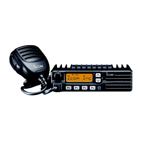
- Page 1 INSTRUCTION MANUAL VHF TRANSCEIVER iF111 iF121 UHF TRANSCEIVER iF211 iF221...
-
Page 2: Important
The transceiver may be damaged. Icom, Icom Inc. and the Icom logo are registered trademarks of Icom Incorporated (Japan) in Japan, the United states, the United King- dom, Germany, France, Spain, Russia and/or other countries. -
Page 3: Table Of Contents
For U.S.A. only ■ Fuse replacement ............15 CAUTION: Changes or modifications to this transceiver, not ■ Cleaning ..............15 expressly approved by Icom Inc., could void your authority to 4 OPTIONS ...............16 operate this transceiver under FCC regulations. 5 SAFETY TRAINING INFORMATION ......17... -
Page 4: Panel Description
PANEL DESCRIPTION ■ Front panel q AF VOLUME CONTROL KNOB e UP/DOWN [ ] KEYS Rotate the knob to adjust the audio output level. ➥ Push to select the operating channel. • Minimum audio level is pre-programmed. ➥ Can be programmed for one of several functions by your dealer. -
Page 5: Function Display
PANEL DESCRIPTION ■ Function display t DEALER-PROGRAMMABLE KEYS [P0] to [P3] Desired functions can be programmed independently by your dealer. y MICROPHONE CONNECTOR Connect the supplied or optional microphone. NEVER connect non-specified microphones. The pin assignments may be different and the transceiver may be damaged. -
Page 6: Programmable Function Keys
[P3], [ ] and [ ] programmable function keys. Displays the CH number, 5-tone indication, DTMF num- Consult your Icom dealer for details concerning your trans- bers, Audible indication, etc. ceiver’s programming. In the following explanations, programmable function names are bracketed. The specific switch used to activate the func- tion depends on programming. - Page 7 PANEL DESCRIPTION • SCAN START/STOP KEY • MONITOR KEY Push this key to start scanning; and push again to Activates one of (or two of) the following functions MONI stop. on each channel independently: • Push and hold the key to unmute the channel (audio is emitted;...
- Page 8 PANEL DESCRIPTION • OUTPUT POWER SELECTION KEYS • CALL KEY Select the transmit output power temporarily, or Transmit a 2-tone, 5-tone code. permanently, depending on the pre-setting. • Call transmission is necessary before you call another station depending on your signaling system. •...
-
Page 9: Panel Description
PANEL DESCRIPTION • SCRAMBLER KEY • USER SET MODE KEY ➥ Push and hold to turn the voice scrambler func- Changes the contents of the items in the User Set SCRM tion ON. mode. Please refer to p. 10. ➥ Push this key to turn the voice scrambler func- •... -
Page 10: Operation
OPERATION ■ Turning power ON ■ Channel selection q Push [ ] to turn the power ON. Several types of channel selection are available. The meth- w If the transceiver is programmed for a start up passcode, ods may differ according to your system setup. input the digit codes as directed by your dealer. -
Page 11: Receiving And Transmitting
OPERATION ■ Receiving and transmitting D Transmitting notes RECEIVING: q Push [ ] to turn the power ON. • Transmit inhibit function w Push [ ] and [ ] to select a channel. The transceiver has several inhibit functions which restrict e When receiving a call, adjust the audio output level to a transmission under the following conditions: comfortable listening level. -
Page 12: D Tx Code Channel Selection
OPERATION D TX code channel selection D DTMF transmission If the transceiver has a [TX CH] key, the display can be tog- If the transceiver has a [DTMF] key, the automatic DTMF gled between the operating channel number (or name) and transmission function is available. - Page 13 OPERATION D User set mode User set mode is accessed at power ON, and allows you to set seldom-changed settings. In this case you can “custom- ize” transceiver operation to suit your preferences and operat- ing style. Entering the user set mode: q While pushing and holding [ ] and [ ], push [POWER]...
-
Page 14: Connection And Maintenance
CONNECTION AND MAINTENANCE ■ Rear panel and connection Optional speaker Antenna (SP-22) R WARNING! NEVER con- nect to a 24 V battery. R WARNING! NEVER re- move the fuse-holder from the DC power cable. red: black: Battery To the antenna connector NOTE: Use the terminals as shown below for the... -
Page 15: Supplied Accessories
CONNECTION AND MAINTENANCE ■ Supplied Accessories q ANTENNA CONNECTOR Connects to an antenna. Contact your dealer about an- tenna selection and placement. w MICROPHONE HANGER Connect the supplied microphone hanger to the vehicle’s ground for microphone on/off hook functions. (See p. 2) e DC POWER RECEPTACLE Connects to a 12 V DC battery. -
Page 16: Mounting The Transceiver
CONNECTION AND MAINTENANCE ■ Mounting the transceiver ■ Optional UT-108 installation The universal mounting bracket supplied with your transceiver Install the optional UT-108 unit as follows: allows overhead mounting. q Turn the power OFF, then disconnect the DC power • Mount the transceiver securely with the 4 supplied screws to a thick cable. -
Page 17: Optional Ut-109 Or Ut-110 Installation
CONNECTION AND MAINTENANCE ■ Optional UT-109 or UT-110 ■ Optional OPC-617 installation installation Install the OPC-617 as shown below. q Turn the power OFF, then disconnect the DC power cable. w Unscrew the 4 cover screws, then remove the bottom cover. -
Page 18: Antenna
CONNECTION AND MAINTENANCE ■ Antenna A key element in the performance of any communication sys- tem is an antenna. Contact your dealer about antennas and the best places to mount them. ■ Fuse replacement Two fuses are installed in the supplied DC power cable. If a fuse blows or the transceiver stops functioning, track down the source of the problem if possible, and replace the dam- aged fuse with a new rated one. -
Page 19: Options
Compact and easy-to-install. performance when used with an Icom transceiver. Input impedance : 4 ø Icom is not responsible for the destruction or damage to an Max. input power : 5 W Icom transceiver in the event the Icom transceiver is used with equipment that is not manufactured or approved by •... -
Page 20: Safety Training Information
Electromagnetic Interference/Compatibility to achieve 1 meter separation distance. In order to ensure this During transmissions, your Icom radio generates RF energy that can distance is met, the installation of the antenna must be mounted possibly cause interference with other devices or systems. To avoid... -
Page 21: Fcc Information
FCC INFORMATION FOR CLASS B UNINTENTIONAL RADIATORS This equipment has been tested and found to comply with the limits for a Class B digital device, pursuant to part 15 of the FCC Rules. These limits are designed to provide reasonable protection against harmful interference in a residential instal- lation. - Page 22 MEMO...
- Page 23 MEMO...
- Page 24 A-6235H-1EX-e Printed in Japan 1-1-32 Kamiminami, Hirano-ku, Osaka 547-0003, Japan © 2003–2009 Icom Inc.
Need help?
Do you have a question about the IC-F111 and is the answer not in the manual?
Questions and answers