Table of Contents
Advertisement
Advertisement
Table of Contents

Subscribe to Our Youtube Channel
Related Manuals for Icom IC-F110


Summary of Contents for Icom IC-F110
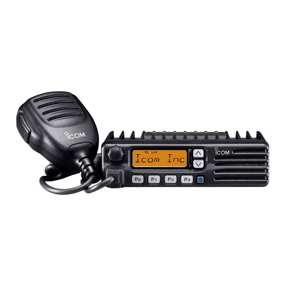
- Page 1 INSTRUCTION MANUAL VHF TRANSCEIVER iF110 UHF TRANSCEIVER iF210...
-
Page 2: Important
NEVER instruction manual contains important operating instructions connect the transceiver to a power source of more for the IC-F110 VHF TRANSCEIVER and IC-F210 UHF than 16 V DC such as a 24 V battery. This connection will ruin TRANSCEIVER. the transceiver. -
Page 3: Table Of Contents
I Fuse replacement ..............17 I Cleaning ................. 17 CAUTION: Changes or modifications to this transceiver, not ex- 5 OPTIONS ................... 18 pressly approved by Icom Inc., could void your authority to operate 6 CE ..................19–20 this transceiver under FCC regulations. -
Page 4: Panel Description
PANEL DESCRIPTION I Front panel q AF VOLUME CONTROL KNOB e UP/DOWN [ ] KEYS ➥Push to select the operating channel. Rotate the knob to adjust the audio output level. ➥Can be programmed for one of several functions by your •... -
Page 5: I Function Display
PANEL DESCRIPTION I Function display t DEALER-PROGRAMMABLE KEYS [P0] to [P3] Desired functions can be programmed independently by your dealer. y MICROPHONE CONNECTOR Connect the supplied microphone or optional DTMF micro- phone for SmarTrunk II operation here. NEVER connect non-specified microphones. The pin assignments may be different and the transceiver may be damaged. -
Page 6: I Programmable Function Keys
[P3], [ ] and [ ] programmable function keys. Displays the CH number, 5-tone indication, DTMF num- Consult your Icom dealer for details concerning your trans- bers, Audible indication, etc. ceiver’s programming. NOTE: When the alphanumeric display blinks and trans-... - Page 7 PANEL DESCRIPTION ¡ ¡ SCAN START/STOP KEY ¡ ¡ MONITOR KEY Push this key to start scanning; and push again Activates one of (or two of) the following functions SCAN A MONI to stop. on each channel independently: SCAN B •...
- Page 8 PANEL DESCRIPTION ¡ ¡ OUTPUT POWER SELECTION KEYS ¡ ¡ CALL KEY Select the transmit output power temporarily, or Transmit a 2-tone, 5-tone code. CALL permanently, depending on the pre-setting. • Call transmission is necessary before you call another station depending on your signaling system. •...
- Page 9 PANEL DESCRIPTION ¡ ¡ SCRAMBLER KEY ¡ ¡ USER SET MODE KEY ➥ Push and hold to turn the voice scrambler func- Changes the contents of the items in the User Set SCRM tion ON. mode. Please refer to p. 10. ➥...
-
Page 10: Operation
OPERATION I Turning power ON I Channel selection q Push [ ] to turn the power ON. Several types of channel selection are available. The meth- ods may differ according to your system setup. w If the transceiver is programmed for a start up passcode, input the digit codes as directed by your dealer. -
Page 11: I Receiving And Transmitting
OPERATION I Receiving and transmitting D Transmitting notes RECEIVING: q Push [ ] to turn the power ON. • Transmit inhibit function w Push [ ] and [ ] to select a channel. The transceiver has several inhibit functions which restrict e When receiving a call, adjust the audio output level to a transmission under the following conditions: comfortable listening level. -
Page 12: D Tx Code Channel Selection
OPERATION D TX code channel selection D DTMF transmission If the transceiver has a [TX CH] key, the display can be tog- If the transceiver has a [DTMF] key, the automatic DTMF gled between the operating channel number (or name) and transmission function is available. -
Page 13: D User Set Mode
OPERATION D User set mode User set mode is accessed at power ON and allows you to set seldom-changed settings. In this case you can “cus- tomize” transceiver operation to suit your preferences and operating style. Entering the user set mode: q While pushing and holding [ ] and [ ], push [POWER]... -
Page 14: Optional Smartrunk
OPTIONAL SmarTrunk II™ OPERATION I SmarTrunk II™ and I SmarTrunk II™ operation conventional modes These features are enabled by a dealer and may not be avail- able in your system. Contact your dealer for details. This transceiver is capable of SmarTrunk II™ functions. D Placing a telephone call The optional UT-105 allows communication in conventional Enter the phone number followed by [1], [M]. -
Page 15: Emergency Call
OPTIONAL SmarTrunk II™ OPERATION D Terminating a call D System busy indication After completing a call, push [#] to disconnect (hang up). If all channels are busy, three low beeps sound after you initi- ate a call. Try the call again later. IMPORTANT!: If one person in the conversation termi- nates a call, all participants will be cut off. -
Page 16: Connection And Maintenance
CONNECTION AND MAINTENANCE I Rear panel and connection Optional speaker Antenna (SP-22) R C A U T I O N ! N E V E R r e- red: move the fuse-holder from the DC power cable. NOTE: Use the terminals as shown below for the cable connections. -
Page 17: I Supplied Accessories
CONNECTION AND MAINTENANCE I Supplied Accessories q ANTENNA CONNECTOR Connects to an antenna. Contact your dealer about an- tenna selection and placement. w MICROPHONE HANGER Connect the supplied microphone hanger to the vehicle’s KEY-STICKER ground for microphone on/off hook functions. (See p. 2) e DC POWER RECEPTACLE Connects to a 12 V DC battery. -
Page 18: I Mounting The Transceiver
CONNECTION AND MAINTENANCE I Mounting the transceiver I Optional UT-105, UT-108 or UT-111 installation The universal mounting bracket supplied with your transceiv- er allows overhead mounting. Install the optional UT-105, UT-108 or UT-111 unit as follows: • Mount the transceiver securely with the 4 supplied screws q Turn the power OFF, then disconnect the DC power cable. -
Page 19: I Optional Ut-109 Or Ut-110 Installation
CONNECTION AND MAINTENANCE I Optional UT-109 or UT-110 I Optional OPC-617 installation installation Install the OPC-617 as shown below. q Turn the power OFF, then disconnect the DC power cable. w Unscrew the 4 cover screws, then remove the bottom cover. -
Page 20: I Antenna
CONNECTION AND MAINTENANCE I Antenna A key element in the performance of any communication sys- tem is an antenna. Contact your dealer about antennas and the best places to mount them. I Fuse replacement A fuse is installed in the supplied DC power cable. If a fuse blows or the transceiver stops functioning, track down the source of the problem if possible, and replace the damaged fuse with a new rated one. -
Page 21: Options
OPTIONS SP-22 EXTERNAL SPEAKER Compact and easy-to-install. Input impedance : 4 Ω Max. input power : 5 W HM-100TN DTMF microphone. SM-25 Desktop microphone. UT-105 SmarTrunk II Logic Board Provides SmarTrunk II capabilities. UT-108 DTMF DECODER UNIT Provides pager and code squelch capabilities. UT-109/UT-110 (#02) VOICE SCRAMBLER UNIT •... - Page 22 DECLARATION OF CONFORMITY We Icom Inc. Japan 0168 1-1-32, Kamiminami, Hirano-ku Osaka 547-0003, Japan Declare on our sole responsibility that this equipment complies with the essential requirements of the Radio and Telecommunications Terminal Equipment Directive, 1999/5/EC, and that any applicable Essential Test Düsseldorf 18th Nov.
- Page 23 EN 60950 (August 1992 +A11) iv) EN 300 086-2 (March 2001) Signature v) EN 300 219-2 (March 2001) About e-marking: Detailed installation notes for Icom mobile transceivers to be fitted into vehicles are available. Please contact your Icom dealer or distributor.
- Page 24 < Intended Country of Use > A-6234H-1EU-q Printed in Japan 1-1-32 Kamiminami, Hirano-ku, Osaka 547-0003 Japan © 2002–2003 Icom Inc.
Need help?
Do you have a question about the IC-F110 and is the answer not in the manual?
Questions and answers