
Subscribe to Our Youtube Channel
Related Manuals for Grizzly G1005Z


Summary of Contents for Grizzly G1005Z
- Page 1 MODEL G1005Z MILL/DRILL OWNER'S MANUAL WARNING: NO PORTION OF THIS MANUAL MAY BE REPRODUCED IN ANY SHAPE OR FORM WITHOUT THE WRITTEN APPROVAL OF GRIZZLY INDUSTRIAL, INC.
-
Page 3: Table Of Contents
Table of Contents INTRODUCTION ..........2 SECTION 5: ACCESSORIES ......27 SECTION 6: MAINTENANCE ......29 SECTION 1: SAFETY ........6 SECTION 7: SERVICE ........30 SECTION 2: POWER SUPPLY ......9 SECTION 3: SET UP ........11 SECTION 8: WIRING ........35 SECTION 9: PARTS ........ -
Page 4: Introduction
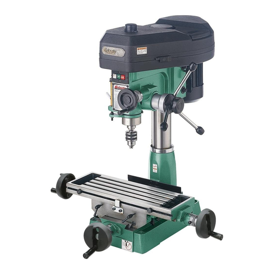
INTRODUCTION Manual Accuracy Contact Info your machine may not exactly match the manual www.grizzly.com... - Page 5 Identification Figure 1.
-
Page 6: Machine Data Sheet
Machine Data Sheet MACHINE DATA SHEET Customer Service #: (570) 546-9663 · To Order Call: (800) 523-4777 · Fax #: (800) 438-5901 MODEL G1005Z MILL/DRILL MILLING MACHINE #25 Weight................................374 lbs. Length/Width/Height......................... 36-1/2 x 34-1/2 x 40 in. Foot Print (Length/Width)........................20-1/2 x 13 in. Type................................ - Page 7 Table Length.............................. 23 in. Table Width............................7-1/2 in. Table Thickness............................. 1-3/4 in. No. Of T Slots..............................4 T Slots Width............................. 1/2 in. T Slots Height............................7/8 in. T Slots Centers............................1-1/2 in. Stud Size..............................3/8 in. Spindle Taper..............................R-8 Spindle Sleeve Diameter.........................2.44 in. End Milling Cap............................
-
Page 8: Section 1: Safety
SECTION 1: SAFETY For Your Own Safety, Read Instruction Manual Before Operating this Machine The purpose of safety symbols is to attract your attention to possible hazardous conditions. This manual uses a series of symbols and signal words intended to convey the level of importance of the safety messages. -
Page 9: Safety Instructions For Machinery
Safety Instructions for Machinery DISCONNECTING POWER SUPPLY. APPROVED OPERATION. INTENDED USE. CHILDREN & BYSTANDERS. STABLE MACHINE. FEED DIRECTION. SECURING WORKPIECE. FORCING MACHINERY. GUARDS & COVERS. UNATTENDED OPERATION. MAINTENANCE & INSPECTION. REMOVING TOOLS. AWKWARD POSITIONS. EXPERIENCING DIFFICULTIES. DANGEROUS ENVIRONMENTS. - Page 10 Additional Safety for Mill/Drills UNDERSTANDING CONTROLS. POWER DISRUPTION. SAFETY ACCESSORIES. MACHINE CARE AND MAINTENANCE. WORK HOLDING. CHUCK KEY SAFETY. DISCONNECT POWER. SPINDLE SPEEDS. CLEAN-UP. STOPPING SPINDLE. CUTTING TOOL INSPECTION. AVOIDING ENTANGLEMENT. BE ATTENTIVE. EXPERIENCING DIFFICULTIES. Like all machinery there is potential danger No list of safety guidelines can be complete.
-
Page 11: Section 2: Power Supply
SECTION 2: POWER SUPPLY Availability Circuit Information For your own safety and protection of property, consult a qualified electrician if you are unsure about wiring practices or electrical codes in your area. Electrocution, fire, equipment damage may occur if machine is not Note: The circuit requirements listed in this man- correctly grounded and ual apply to a dedicated circuit—where only one... -
Page 12: Extension Cords
Grounding Requirements Serious injury could occur if you connect the machine to power before completing the setup process. DO NOT connect to power until instructed later in this manual. For 110V operation: NOTICE The Model G1005Z is prewired for 110V operation. -
Page 13: Section 3: Set Up
SECTION 3: SET UP Needed for Setup This machine presents serious injury hazards to untrained users. Read through this entire manu- al to become familiar with the controls and opera- Description tions before starting the machine! Wear safety glasses dur- ing the entire set up pro- cess! Unpacking... - Page 14 Hardware Recognition Chart...
- Page 15 Inventory Main Components: (Figure 4) Figure 4. Other Components and Hardware: NOTICE Some hardware/fasteners on the inventory list may arrive pre-installed on the machine. Check these locations before assuming that any items from the inventory list are miss- ing.
- Page 16 Cleanup Gasoline and petroleum products have low flash points and can explode or cause fire if used to clean machinery. Avoi d u sing t h e s e p r o d u c t s to cl e a n machin e r y. Many cleaning solvents toxic inhaled.
-
Page 17: Site Considerations
Site Considerations Weight Load Physical Environment Machine Data Sheet Space Allocation Electrical Installation See below for required space allocation. Lighting Children or untrained people may be seriously injured by this machine. Only install in an access restricted location. Figure 6. - Page 18 Mounting Assembly To assemble the Model G1005Z: SECTION 5: ACCESSORIES Page 27 Figure 9 Figure 9. Figure 10 Figure 7. Figure 10. Figure 8.
- Page 19 Test Run Spindle Break-In NOTICE Successfully complete the spindle break-in procedure to avoid rapid wear of spindle components when placed into operation. Troubleshooting Page 30 To perform the spindle break-in procedure: To test run the machine: Choosing Milling Speeds Page 23...
-
Page 20: Section 4: Operations
OMMEND that you read books, trade maga- zines, or get formal training before begin- ning any projects. Regardless of the con- tent in this section, Grizzly Industrial will not be held liable for accidents caused by lack of training. Figure 11. - Page 21 To install an arbor: To install end mill tooling: To remove an arbor: To install the drill chuck: Figure 12. Figure 13 Note: Once the chuck is seated on the arbor, it is a semi-permanent connection. If you wish to use a different chuck, we recommend obtaining a new arbor for that chuck.
- Page 22 To install a drill bit: Table Figure 14 Note: Make sure the bit is not trapped between the edges of two jaws, as it will not be secure enough to use for drilling. To remove a drill bit: Figure 14. Longitudinal Feed: Larger bits turning at slower speeds tend to grab the workpiece aggressively.
-
Page 23: Graduated Dials
Graduated Dials Micro-Downfeed Handwheel Figure 15 Backlash Note: It is up to you to determine an acceptable amount of backlash for your system. The frictional wear on your lead screw increases as backlash is reduced. Attempting to completely eliminate back- lash can place excessive wear on your lead screw Figure 15. -
Page 24: Quill Lock
Quill Lock Figure 17 To lock the quill in place: Figure 16 Figure 17. To set the depth stop: Figure 16. To unlock the quill: To set the spindle return distance: Depth Stop Note: The scale on the depth stop can be recali- brated if it gets moved or has changed since the factory setting. -
Page 25: Choosing Drilling Speeds
Choosing Milling Speeds Failure to follow RPM and Feed Rate Guidelines may result in ejected parts or broken tools. Parts ejected at high speeds can cause serious injury! Choosing Drilling Speeds To determine the needed RPM: Using the Drill Bit Speed Chart Figure 18 Page 24 (Cutting Speed x 4) / Tool Diameter =... - Page 26 Twist/Brad Point Drill Bits Soft Wood Hard Wood Plastic Brass Aluminum Mild Steel 1/16" – 3/16" 3000 2500 2500 2500 3000 2500 13/64" – 3/8" 2000 1500 2000 1250 2500 1250 25/64" – 5/8" 1500 1500 1500 11/16" – 1" 1000 1000 Spade/Forstner Bits...
-
Page 27: Changing Speeds
Changing Speeds Page 24 For Example: Figure 23 Note: Both belts may have to be removed To change speeds: before certain speed changes can be made. It is normal for the idler bracket to move in response to a belt change. Figure 21 Figure 21. -
Page 28: Drilling Guidelines
SOFT MATERIAL: Drilling Guidelines LUBRICANT: Lubrication Suggestions Page 23 DRILLING ACCURACY: For safe operation and optimum results, it is very important to follow these guidelines when drilling SECURING WORKPIECE TO TABLE: PLUG/ROSETTE CUTTERS: CLEARING CHIPS: 5-FLUTE/2-FLUTE CUTTERS: PROTECTING TABLE: SPADE BITS AND PLASTIC: USING CORRECT SPEEDS: HOLE SAWS: Drill Bit Speed Chart... -
Page 29: Section 5: Accessories
To minimize this risk, only install accessories recommended for this machine by Grizzly. NOTICE Refer to the newest copy of the Grizzly Catalog for other accessories available for this machine. G5944—Stand for Model G1005Z Mill/Drill Figure 25. - Page 30 ® G5971 — 3 ⁄ " Swivel Base Milling Vise G5562—SLIPIT 1 Qt. Gel G5972—4" Swivel Base Milling Vise G5563—SLIPIT ® 12 oz Spray ® G5973—5" Swivel Base Milling Vise G2871—Boeshield T-9 12 oz Spray G5973—5" Swivel Base Milling Vise G2870—Boeshield ®...
-
Page 31: Section 6: Maintenance
SECTION 6: MAINTENANCE Unpainted Cast Iron Always disconnect power to the machine before performing maintenance. Failure to do this may result in serious person- al injury. Schedule Lubrication Daily Check: Weekly Maintenance: Figure 32 Cleaning Figure 32. -
Page 32: Section 7: Service
SECTION 7: SERVICE Troubleshooting Motor & Electrical Page 37 Page 37... - Page 33 Symptom Possible Cause Possible Solution Page 25 Operation Symptom Possible Cause Possible Solution Page 33...
- Page 34 Symptom Possible Cause Possible Solution...
-
Page 35: Depth Stop Calibration
Depth Stop Feed Shaft Spring Calibration Tension To calibrate the depth stop: Figure Wear safety glasses when adjusting springs. Serious injury may occur if this warning is ignored! To adjust the feed shaft spring tension: Figure 34 Figure 33. Figure 34. - Page 36 A high tension coiled spring is underneath the cover. Put on heavy leather gloves to Note: It is important to keep a good grip protect yours hands from possible injury during this step. Letting go of the cover will when removing the cover. cause the spring to rapidly uncoil, which could cause serious injury! Figure 35.
-
Page 37: Section 8: Wiring
SECTION 8: WIRING Wiring Safety Instructions SHOCK HAZARD. WIRE/COMPONENT DAMAGE. MOTOR WIRING. MODIFICATIONS. CAPACITORS/INVERTERS. WIRE CONNECTIONS. CIRCUIT REQUIREMENTS. EXPERIENCING DIFFICULTIES. The photos and diagrams included in this section are best viewed in color. You can view these pages in color at www.grizzly.com. -
Page 38: Electrical Components
Electrical Components Figure 36. READ ELECTRICAL SAFETY ON PAGE 35! -
Page 39: Wiring Diagram
Wiring Diagram COLOR KEY WARNING! SHOCK HAZARD! Disconnect power before working on wiring. Ground 6-15 Plug (As Recommended) Ground Neutral 5-15 Plug (As Included) ( RE-WIRED TO 220V ) Circuit Circuit Breaker Breaker MOTOR MOTOR ( 110V ) ( 220V ) READ ELECTRICAL SAFETY ON PAGE 35! -
Page 40: Section 9: Parts
SECTION 9: PARTS Main Assembly Breakdown... - Page 41 Main Assembly Parts List PART # DESCRIPTION PART # DESCRIPTION P1005001 HEAD BODY PSB01 CAP SCREW 1/4-20 X 5/8 P1005002 CHUCK ARBOR BOLT 7/16-20 P1005044 WORM SHAFT P1005003 SPINDLE LOCKNUT 34 X 16 P1005045 BUSHING P1005004 SPINDLE PULLEY P1005Z046 CRANK ARM P1005005 OUTER BEARING PLATE P1005Z048...
- Page 42 Table Breakdown...
- Page 43 MUST maintain the original location and readability of the labels on the machine. If any label is removed or becomes unreadable, REPLACE that label before using the machine again. Contact Grizzly at (800) 523-4777 or www.grizzly.com to order new labels. -41-...
-
Page 45: Warranty Card
WARRANTY CARD The following information is given on a voluntary basis. It will be used for marketing purposes to help us develop better products and services. Of course, all information is strictly confidential. Note: We never use names more than 3 times. _____________________________________________________________________ _________________________________________________________________________________ _________________________________________________________________________________... -
Page 47: Warranty And Returns
WARRANTY AND RETURNS... - Page 48 ® Buy Direct and Save with Grizzly – Trusted, Proven and a Great Value! ~Since 1983~ Visit Our Website Today For Current Specials! ORDER 24 HOURS A DAY! 1-800-523-4777...
Need help?
Do you have a question about the G1005Z and is the answer not in the manual?
Questions and answers