Grizzly G1006 Owner's Manual
Heavy-duty mill/drill
Hide thumbs
Also See for G1006:
- Instruction manual (23 pages) ,
- Parts list (7 pages) ,
- Owner's manual (48 pages)
Table of Contents
Advertisement
Quick Links
Download this manual
See also:
Instruction Manual
Advertisement
Table of Contents

Subscribe to Our Youtube Channel
Related Manuals for Grizzly G1006


Summary of Contents for Grizzly G1006
- Page 1 MODEL G1006/G1007 HEAVY-DUTY MILL/DRILL OWNER'S MANUAL (For models manufactured since 09/09) WARNING: NO PORTION OF THIS MANUAL MAY BE REPRODUCED IN ANY SHAPE OR FORM WITHOUT THE WRITTEN APPROVAL OF GRIZZLY INDUSTRIAL, INC.
- Page 2 This manual provides critical safety instructions on the proper setup, operation, maintenance, and service of this machine/tool. Save this document, refer to it often, and use it to instruct other operators. Failure to read, understand and follow the instructions in this manual may result in fire or serious personal injury—including amputation, electrocution, or death.
-
Page 3: Table Of Contents
Table of Contents INTRODUCTION ..........2 SECTION 5: ACCESSORIES ......31 SECTION 6: MAINTENANCE ......33 SECTION 1: SAFETY ........10 SECTION 7: SERVICE ........37 SECTION 2: POWER SUPPLY ...... 13 SECTION 8: WIRING ........39 SECTION 9: PARTS ........41 SECTION 3: SETUP ........ -
Page 4: Introduction
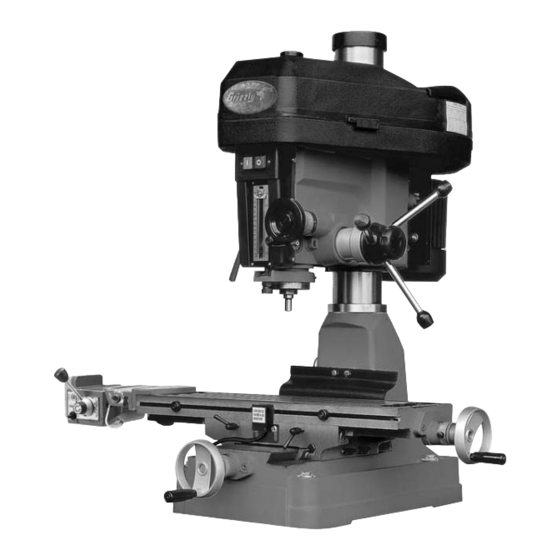
The differ- ence between the two models In milling operations, the location of the cutting www.grizzly.com tool is stationary while the workpiece is fed into the cutter by moving the table. In drilling operations, the workpiece is held sta-... - Page 5 Identification G1007 G1006 Figure 3. Identification. Pinion Hub Lock Knob A. Junction Box K. X-Axis Handwheels B. Headstock Height Crank Longitudinal Stops C. Return Spring Assembly M. Y-Axis Lock Handles D. Quill Lock N. X-Axis Lock Handles E. ON/OFF Swtich O.
- Page 6 Customer Service #: (570) 546-9663 · To Order Call: (800) 523-4777 · Fax #: (800) 438-5901 Weight................................566 lbs. Width (side-to-side) x Depth (front-to-back) x Height..............50 x 40 x 48-1/2 in. Footprint (Length x Width)..........................24 x 16 in. Type................................
- Page 7 Table Length.............................. 32 in. Table Width............................9-1/2 in. Table Thickness............................ 1-7/8 in. Number of T-Slots............................4 T-Slots Width............................0.625 in. T-Slots Height............................7/8 in. T-Slots Centers............................ 2-1/16 in. Stud Size..............................1/2 in. Spindle Taper............................... R-8 End Milling Capacity..........................3/4 in. Face Milling Capacity...........................
- Page 8 Customer Service #: (570) 546-9663 · To Order Call: (800) 523-4777 · Fax #: (800) 438-5901 Weight................................566 lbs. Width (side-to-side) x Depth (front-to-back) x Height..............50 x 40 x 48-1/2 in. Footprint (Length x Width)..........................24 x 16 in. Type................................
- Page 9 Spindle Travel.............................. 5 in. Swing..............................15-7/8 in. Longitudinal Table Travel........................23-1/2 in. Cross Table Travel............................7 in. Ram Travel..............................12 in. Head Travel............................5-1/4 in. Head Tilt (Left-to-Right)........................360 deg. Maximum Distance Spindle to Column......................8 in. Maximum Distance Spindle to Table......................18 in. Drilling Capacity for Cast Iron........................
- Page 10 ISO Factory ..............................ISO 9001 Country Of Origin ............................... China Warranty ................................1 Year Serial Number Location ...................... ID Label on Head Casting Assembly Time ............................1-1/2 hours Clutch-Type Downfeed Mechanism Graduations in Inches Exclusive Fine Downfeed is Graduated in .001" and is Engaged by Clutch-Type Mechanism Heavy Duty 12 Speed Tapered Roller Bearing Spindle Top Quality Workmanship Throughout Push Button Switch with Thermal Overload Protector...
-
Page 11: Glossary Of Terms
Glossary Of Terms VERY Arbor: Gib: Collet: Headstock: Knee: Cutting Speed: Lead Screw: Dial Indicator: Peripheral Milling: Dividing Head: Ram: Down or Climb Milling: Saddle: End Milling: Side Milling: Face Milling: Slitting and Cutting Off: Feed Rate: Spindle: Fixture: Turret: Form Milling: Ways: Gang Milling:... -
Page 12: Section 1: Safety
SECTION 1: SAFETY For Your Own Safety, Read Instruction Manual Before Operating this Machine The purpose of safety symbols is to attract your attention to possible hazardous conditions. This manual uses a series of symbols and signal words intended to convey the level of impor- tance of the safety messages. - Page 13 DISCONNECTING POWER SUPPLY. GUARDS & COVERS. NEVER STAND ON MACHINE. APPROVED OPERATION. STABLE MACHINE. DANGEROUS ENVIRONMENTS. AWKWARD POSITIONS. ONLY USE AS INTENDED. UNATTENDED OPERATION. USE RECOMMENDED ACCESSORIES. MAINTAIN WITH CARE. CHILDREN & BYSTANDERS. CHECK DAMAGED PARTS. REMOVE ADJUSTING TOOLS. MAINTAIN POWER CORDS. SECURING WORKPIECE.
-
Page 14: Additional Safety For Mills
Additional Safety for Mills UNDERSTANDING CONTROLS. MACHINE CARE AND MAINTENANCE. SAFETY ACCESSORIES. DISCONNECT POWER. WORK HOLDING. CHUCK KEY SAFETY AVOIDING ENTANGLEMENT SPINDLE SPEEDS. TOOL HOLDING. POWER DISRUPTION. CLEAN-UP. CUTTING TOOL INSPECTION. SPINDLE DIRECTION CHANGES. STOPPING SPINDLE. BE ATTENTIVE. No list of safety guidelines can be complete. Like all machinery there is potential danger Every shop environment is different. -
Page 15: Section 2: Power Supply
SECTION 2: POWER SUPPLY Availability Circuit Information For your own safety and protection of property, consult an electrician if you are Electrocution, fire, unsure about wiring practices or electrical equipment damage may codes in your area. occur if machine is not correctly grounded and Note: The circuit requirements listed in this man- connected to the power... -
Page 16: Extension Cords
Grounding Requirements GROUNDED 6-15 RECEPTACLE 6-15 PLUG For 110V operation: Figure 5. GROUNDED 5-15 RECEPTACLE 5-15 PLUG Figure 4. Extension Cords SHOCK HAZARD! Two-prong outlets do not meet the grounding requirements for this machine. Do not modify or use an adapter on the plug provided—if it will not fit the outlet, have a qualified electrician install the proper outlet with a verified ground. -
Page 17: Section 3: Setup
SECTION 3: SETUP Unpacking This machine presents serious injury hazards to untrained users. Read through this entire manu- al to become familiar with please call us immediately the controls and opera- at (570) 546-9663 for advice. tions before starting the machine! Otherwise, filing a freight claim can be difficult. - Page 18 G1007 Only Inventory In addition to the parts shown in Figure 6, the Model G1007 comes with the power feed and its attachment accessories. Power Feed (G1007 Only) (Figure 7) K. Cap Screws ¼-20 x 1-½ (End Stops) ..2 L.
- Page 19 Cleanup Gasoline or products with low flash points can explode or cause fire if used to clean machin- ery. Avoid cleaning with these products. Many cleaning solvents are toxic if concentrat- ed amounts are inhaled. Only work in a well-venti- lated area.
-
Page 20: Site Considerations
Site Considerations Weight Load Physical Environment Machine Data Sheet Space Allocation Electrical Installation See below for required space allocation. Lighting Children or untrained people may be seriously injured by this machine. Only install in an access restricted location. 50" 40" Figure 9. - Page 21 Table clamping kits are available through the nuts are used to secure the drill press to the Grizzly Catalog and must be purchased sepa- workbench. rately. See Accessories on Page 31. This table will accept "...
- Page 22 Power Feed Clamping Bracket (G1007 Only) The Model G1007 features a 110V auto-feed mechanism which allows hands-free, side-to-side passes while milling. Variable-speed feed control makes flat surface milling more consistent. Mounting Bolts To install the power feed: Attach the 2 "...
- Page 23 Plug the rapid switch cord into the receptacle Remove the center travel stop at the front of provided on the bottom of the power feed the table. Save the mounting bolts. body. Secure the switch bracket to the front of the Screw the knob onto the direction handle.
- Page 24 Handwheels Head Crank There are three handwheels provided with the The head crank secures to the left side of the machine that control table movement. The Model machine and is used to adjust the height of the G1007 only uses two of the handwheels. headstock.
- Page 25 Feed Levers Collet/Arbor The feed levers control the up and down move- The Model G1006/G1007 feature an R-8 spindle ment of the spindle which accepts many industrial collets and arbors. To mount the feed levers to the machine: To install a collet or an arbor: Screw a black knob onto an end of each of Release the latches on the head cover and the three chrome feed levers.
- Page 26 To remove a collet or an arbor: Drill Chuck/Arbor 1. Loosen the hex head at the top of the drawbar (2 or 3 turns). Your Mill/Drill has been pre-fitted with a drill chuck arbor that has an R-8 shank and a Jacob’s Taper. 2.
-
Page 27: Power Connection
Fly Cutter/Arbor Power Connection All types of milling cutters and drill bits are sharp. It is recommended that these not be handled directly. Use paper towels to hold sharp tooling to avoid cuts to your hands. Be careful while handling them and store them in a child safe location. -
Page 28: Test Run
Test Run Troubleshooting Page 37 To test run the machine:... -
Page 29: Section 4: Operations
Regardless of the content in this section, Grizzly Industrial will not be held liable for accidents caused by lack of training. Handwheel Figure 28. Setting dial indicators to zero. -
Page 30: Spindle Height
Note: Locking out the levered downfeed Spindle Height will transfer control to the handwheel. The handwheel will not function if the locking knob is loose. You have two options for spindle height adjust- ment—a drill press style, levered downfeed and Loosen the setscrew on the rim surface of a micro adjustment handwheel. -
Page 31: Depth Stop
Depth Stop Head Height The depth stop is used to control the range of The head height on this Mill/Drill can be adjusted downward movement by the drill bit or cutter. for various applications. Maximum depth is 5". To adjust the head height: To calibrate the depth stop: Loosen the two head locking nuts located on Make sure the spindle is drawn all the way up... -
Page 32: Speed Changes
Loosen the two idler pulley bolts that hold the Speed Changes center pulley system in place, so the pulley will float (Figure 33). The Model G1006/G1007 is capable of twelve dif- ferent speed settings. Different types of cuts and Idler Pulley Bolts types of materials require varying speeds. -
Page 33: Section 5: Accessories
See the current Grizzly catalog for full specifica- of serious personal injury. To minimize this tions. Features: 4.330" overall height (horizontal), risk, only install accessories recommended 6.750"... - Page 34 G9324—Boring Head Combo Set G9760—20-PC. 2 & 4 Flute TiN End Mill Set. Hardened and ground adjusting screws along Includes these sizes and styles in two and four with a wide base design guarantee a long life and flute styles: ", ", ",...
-
Page 35: Section 6: Maintenance
SECTION 6: MAINTENANCE Cleaning and Protecting Always disconnect power to the machine before performing maintenance. Failure to do this may result in serious person- al injury. Schedule Daily Check: • Loose mounting bolts. • Damaged cutting tools. • Worn or damaged wires. •... - Page 36 Lubrication V-Belts Inspect regularly for tension and wear. Replace Points requiring periodic lubrication are: when necessary with a size B-42 belt for the spindle pulley to the idler pulley belt and a size The main column. A light film of oil (SAE 30) B-34 belt from the idler pulley to the motor pulley will smooth action and prevent rust and cor- belt.
-
Page 37: Return Spring
Return Spring Do not completely remove the cover! If you remove the spring cover, the spring will uncoil rapidly and create a great risk of injury. The spring’s tail is located on the perim- eter of the spring housing. This part may Put on gloves and pull the spring cover out be sharp! Use leather gloves or a heavy until the notches just clear the roll pin. -
Page 38: Table Leadscrews
Tighten the adjustment screw. Table Leadscrews Test the adjustment by turning one of the side handwheels. You should detect less than When you turn the handwheels to adjust the posi- 0.010" of play. tion of the table, you will notice slight play in the handwheel before the table begins to move. -
Page 39: Section 7: Service
SECTION 7: SERVICE Note: Please gather the serial number and manufacture date of your machine before calling. Troubleshooting Motor & Electrical Machine does not 1. Plug/receptacle is at fault or wired 1. Test for good contacts; correct the wiring. start or a breaker incorrectly. - Page 40 Motor & Electrical (Continued) Machine has Motor or component is loose. Inspect/replace stripped or damaged bolts/ vibration or noisy nuts, and re-tighten with thread locking fluid. operation. V-belts are slapping belt cover; are Replace/re-tension V-belts. worn or loose. Belt pulley is loose. Replace shaft, pulley, setscrew, and key as required.
-
Page 41: Section 8: Wiring
SECTION 8: WIRING Note: Please gather the serial number and manufacture date of your machine before calling. This information can be found on the main machine label. Wiring Safety Instructions SHOCK HAZARD. WIRE/COMPONENT DAMAGE. MOTOR WIRING. MODIFICATIONS. CAPACITORS/INVERTERS. WIRE CONNECTIONS. CIRCUIT REQUIREMENTS. -
Page 42: Wiring Diagram
Wiring Diagram 110 Volt Wiring (Pre-Wired) Reset Button Cord to Switch Green Ground Motor Connection Box Power Cord VOLTAGE CONVERSION TO 220V 220 Volt Wiring 1) Disconnect power from machine! To minimize the risk of electrocution, fire, 2) Rewire motor to 220V. or equipment damage, voltage conversion 3) Replace power cord plug with a must be done by an electrician or qualified... -
Page 43: Section 9: Parts
SECTION 9: PARTS Head Breakdown 101-1 374A 306A 85V2** 101A 310A 324-1 371A 333A 393A 304A 331-1 370-1 337-1 332A 304-1 343-1 316A 367V2 320-1 317-1 367V2-4 367V2-1 367V2-5 367V2-2 367V2-6 367V2-7 367V2-3 367V2-8 * This part appears on machines produced prior to 07/08. **This part appears on machines produced after 07/08. -
Page 44: Head Parts List
Head Parts List REF PART # DESCRIPTION PART # DESCRIPTION PSW03-1 KNOB P1006326 CLAMP NUT 3/8-16 85V2 PSB01 CAP SCREW 1/4-20 X 5/8 P1006327 SPECIAL SCREW 3/8-16 X 38 P1006101 CRANK BRACKET P11261103 SPRING COVER ASSY 101-1 P1006101-1 OIL CUP P1006330 SPRING BASE 76 X 76 X 19 101A P1006101A CRANK BRACKET ASSEMBLY... - Page 45 Column & Table Parts Breakdown * This part appears on machines produced prior to 07/08. **This part appears on machines produced after 07/08.
- Page 46 Column & Table Parts List PART # DESCRIPTION REF PART # DESCRIPTION PB07 HEX BOLT 5/16-18 X 3/4 P1006416 SADDLE PSB07 CAP SCREW 5/16-18 X 3/4 P1006417 BOTTOM WAY COVER CLAMP PRP10M ROLL PIN 5 X 36 418-1 P1006418-1 WAY COVER ASSEMBLY P1006168 OIL CUP P1006420...
-
Page 47: Power Feed
Power Feed PART # DESCRIPTION PART # DESCRIPTION 231V2 P1007231V2 POWER FEED ASSY AL-310S V2.09.09 231V2-5 P1007231V2-5 LIMIT SWITCH CORD 231V2-1 P1007231V2-1 POWER FEED MOUNTING BRACKET 231V2-6 P1007231V2-6 LIMIT SWITCH ASSEMBLY 231V2-2 P1007231V2-2 POWER FEED LEXAN GEAR 231V2-7 P1007231V2-7 ON/OFF SWITCH 231V2-3 P1007231V2-3 MAIN DRIVE GEAR 231V2-8... -
Page 48: Label Placement
Safety labels help reduce the risk of serious injury caused by machine hazards. If any label comes off or becomes unreadable, the owner of this machine MUST replace it in the original location before resuming operations. For replacements, contact (800) 523-4777 or www.grizzly.com. -
Page 49: Warranty Card
WARRANTY CARD The following information is given on a voluntary basis. It will be used for marketing purposes to help us develop better products and services. Of course, all information is strictly confidential. Note: We never use names more than 3 times. _____________________________________________________________________ _________________________________________________________________________________ _________________________________________________________________________________... -
Page 51: Warranty & Returns
WARRANTY & RETURNS 1 year... - Page 52 ® Buy Direct and Save with Grizzly – Trusted, Proven and a Great Value! ~Since 1983~ Visit Our Website Today For Current Specials! ORDER 24 HOURS A DAY! 1-800-523-4777...
Need help?
Do you have a question about the G1006 and is the answer not in the manual?
Questions and answers