Advertisement
Quick Links
Advertisement

Related Manuals for GReddy Supercharger Kit


Summary of Contents for GReddy Supercharger Kit
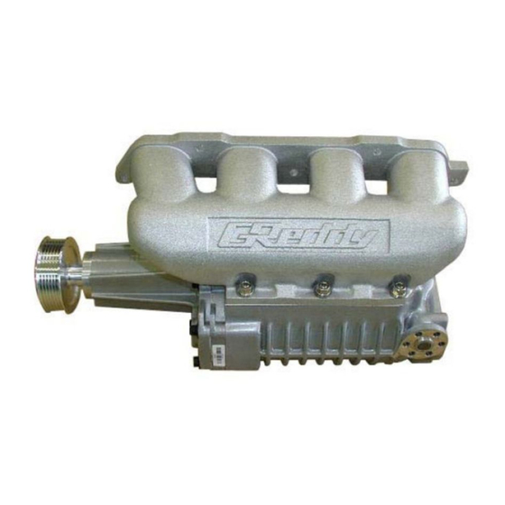
- Page 1 GReddy Supercharger Kit 2000-2002 Toyota Celica GT-S (ZZT231) MP62 Supercharger kit ―1―...
- Page 2 2. If installed by an untrained person, it may cause damage to the kit as well as the vehicle. 3. GReddy Performance Products Inc. is not responsible for any damage to the vehicle’s electrical system caused by improper installation. Make sure to follow the instruction and pay attention to the “Important”, “Warning!”...
-
Page 3: Parts List
1.Parts List 1.Supercharger MP62 (W/ Pulley) 1 2.Intake Manifold 1 3.Intake Tube 1 4.Tensioner Pulley 1 5.Supercharger Belt (6PK-2475) 1 6.Alternator Bracket, Upper 1 7. 〃 Lower 1 8. 〃 Floating Nut 1 9.Oil Dip Stick Guide 1 10.Spacer, Tensioner Pulley 1... - Page 4 Part List Diagrams/Pictures 1 2 3 4 5 6 7 8 9 10 11 12 13 14 15 16 17,18 19 20 21 22 23 24~32 ―4―...
- Page 5 2.OEM Parts Removal Please refer to factory repair manual for OE component removal guidance. 2-1 Safely remove pressure from fuel lines. (1) Remove the circuit-opening relay located in the fuse box in the left side of the engine bay. [ C/O : circuit opening relay] (2) Crank the motor to remove fuel pressure.
- Page 6 3.Kit Install 3-1 OE ventilation Tube No. 1 Modification Remove the bracket from the ventilation tube in 2-13. Install back to same location. ※ After removing bracket, make sure to de-burr and paint surface of modified area. Please use safety glasses and a mask to prevent injury.
- Page 7 3-3 Kit Supercharger assembly (1) Screw in the provided stud bolts onto the supercharger outlet flange and apply silicone sealant to the flange surface. Attach Kit intake manifold to the supercharger. ※ Try to prevent sealant from protruding to the inside of the manifold.
- Page 8 3-5 Kit Oil Dip Stick Installation (1) Remove the O-ring from the OE dipstick guide and Kit dipstick OE dipstick place it on the Kit dipstick guide. guide guide ※ If the O-ring is damaged, please replace with OEM part. 〈Part №9〉...
- Page 9 3-8 Kit V Ribbed Belt Installation. Adjust the tensioner pulley toward the front of the vehicle to adjust belt tension. 〈Part №5〉 VP : Vane Pump Pulley CK : Crank Pulley CC : Cooler Compressor WP : Water Pump Pulley AL...
- Page 10 (3) Cut off the OE injector harness connectors and replace with Kit injector harness connectors. ※ Mark or label harness wires to ensure that they are connected to the proper pin on the injector. ※ Do not connect the injector connector at this time. Solder procedure ①...
- Page 11 3-11 Kit Intake Tube Installation (1) Remove the studs on the OE intake air surge tank and screw them into the Kit intake tube. 〈Part №3〉 (2) Attach the Kit intake tube to the supercharger inlet. At the same time, place the spacer between the Kit intake tube bracket and “Thread A”...
- Page 12 For Vehicles With Auto Cruise Control ① Place the rubber grommets removed in step 2-7 between the cruise control unit and the provided auto cruise control brackets. Use OE screws to secure bracket to unit. 〈Part №15〉 Bracket A Bracket B ②...
- Page 13 3-13 Kit e-manage Ultimate installation (1) Remove the ECM box cover and disconnect and remove connector A, B, and ground from the box. Remove the electrical tape to all the harness grommet to move freely. The ECM is on the right side of the engine bay.
- Page 14 e-manage Ultimate Connector Harness Pin Location C B A ※ Viewing from wire harness side. Ultimate OE ECM Signal (Color) Signal Pin № Pin № 3 Ignition Input CH4(PL/W) A_11 Ignition Pulse IGT2 To ECM 4 Ignition Input CH2(O/W) A_12 Ignition Pulse IGT3...
- Page 15 These wire are outlined in the e-manage diagram. These wires will not be used in this kit. electrical tape to cover the ends of the wires to prevent short circuit. №14 VTEC Output(Y) №33 Crank Angle Signal(GY/W) №39 Camshaft Angle Signal(GY/B) №40...
- Page 16 (6) Route the e-manage ultimate wire harness safely though the engine bay and use cable ties to secure the harness and prevent it from moving. Place the A/C line grommet in its original location. ※ Use cable ties to secure the harness to the accelerator control cable secure areas. 〈Part №18〉 (7) Adjust the dipswitches on the e-manage Ultimate unit.
- Page 17 It is very important that you monitor the boost pressure, and make sure not to over boost. Over boosting can cause engine damage. o GReddy Performance Products, Inc. is not responsible for any engine damage caused by over boosting (increased boost), modification to the kit, and/or misuse of the product. NO WARRANTY is offered.
- Page 18 Front Fender Apron & Dash Panel...
- Page 19 Cylinder Head...
- Page 20 Suspension Cross Member and Under Cover...
- Page 21 Switch and Relay...
- Page 22 Air Cleaner...
- Page 23 Fuel Injection System...
- Page 24 Ventilation Hose...
- Page 25 Cylinder Block...
- Page 26 Manifold...
Need help?
Do you have a question about the Supercharger Kit and is the answer not in the manual?
Questions and answers