GReddy INTERCOOLER KIT Installation Manual
For nissan gt-r r35 2012
Hide thumbs
Also See for INTERCOOLER KIT:
- Instruction manual (9 pages) ,
- Installation manual (9 pages) ,
- Installation manual (13 pages)
Advertisement
Quick Links
Download this manual
See also:
Instruction Manual
SPEC-R
SPEC-R HG
SPEC-R
SPEC-R
Please read the Installation Manual before installing.
Please read the Installation Manual before installing.
Please read the Installation Manual before installing.
Please read the Installation Manual before installing.
•
Keep this manual for future reference.
Keep this manual for future reference.
Keep this manual for future reference.
Keep this manual for future reference.
•
Model
GT-R
Specs
Specs : : : : Cross
Specs
Specs
Cross
Cross- - - - fl fl fl flow Type
Cross
ow Type
ow Type
ow Type
Designed for the Greddy Turbo Kit( ( ( ( TD
Designed for the Greddy Turbo Kit
Designed for the Greddy Turbo Kit
Designed for the Greddy Turbo Kit
If used with the OEM Turbo, GReddy Airinx Kit required.
Not compatible with the stock air box.
Stock windshield washer tank not compatible with GReddy Intercooler Kit.
GReddy Windshield Washer Tank sold separately.
Stock Intercooler Air Duct is not compatible with GReddy Intercooler Kit.
Using this product may void your warranty from Nissan Motor Co., Ltd. Corporation
Using this product may void your warranty from Nissan M
Using this product may void your warranty from Nissan M
Using this product may void your warranty from Nissan M
NISSAN GT-R
NISSAN
NISSAN
NISSAN
(VR
(VR
(VR38
(VR
38
38DETT)
38
Full KIT
Full
Full
Full
Installation Manual
Installation Manual
Installation Manual
Installation Manual
Chassis Code
CBA-R35
TD 06
06 SH
SH- - - - 20
TD
TD
06
06
SH
SH
Designed to be used on the Nissan R35 GTR. Please do not
attempt to use on other model vehicles.
INTERCOOLER ER ER ER KIT
INTERCOOL
INTERCOOL
INTERCOOL
GT-R R R R R 35
GT-R
GT-R
DETT)
DETT)
DETT)
HG TYPE
TYPE29
HG
HG
TYPE
TYPE
KIT
KIT
KIT
Engine Code
VR38DETT
20 G G G G ) ) ) )
20
20
otor Co., Ltd. Corporation
otor Co., Ltd. Corporation
otor Co., Ltd. Corporation
KIT
KIT
KIT
35
35
35
29
29
29
Year
07.12~
Advertisement

Related Manuals for GReddy INTERCOOLER KIT


Summary of Contents for GReddy INTERCOOLER KIT
- Page 1 Stock windshield washer tank not compatible with GReddy Intercooler Kit. GReddy Windshield Washer Tank sold separately. Stock Intercooler Air Duct is not compatible with GReddy Intercooler Kit. Designed to be used on the Nissan R35 GTR. Please do not attempt to use on other model vehicles.
-
Page 2: Parts List
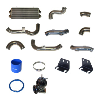
1 1 1 1 . . . . Parts List Parts List Parts List Parts List 1.Intercooler TYPE-29 2.Intake tube I-1 (70 φ aluminum elbow) 3. 〃 I-2 (70 φ aluminum) 4. 〃 I-3 (70 φ aluminum) 5. 〃 I-4 (70... -
Page 3: Parts List Diagram
Parts List Diagram Parts List Diagram Parts List Diagram Parts List Diagram 1 2 3 4 5 6 7 8 9 10 11 12 13 ―2―... - Page 4 14 15~19 20 Blow Off Valve Parts List Blow Off Valve Parts List Blow Off Valve Parts List Blow Off Valve Parts List 1. Blow off valve 6. Hose Clamp size #16 ×2 ×4 2. Hose attachment 29 φ 7. Blow off valve gasket ×2...
-
Page 5: Piping Layout
Piping Layout Piping Layout Piping Layout Piping Layout Throttle RH Throttle RH Throttle RH Throttle RH Throttle LH Throttle LH Throttle LH Throttle LH № № № № 5 5 5 5 № № № № 20 20 20 20 I I I I - - - - 4... - Page 6 2 2 2 2 . . . . Removal of Stock Parts Removal of Stock Parts Removal of Stock Parts Removal of Stock Parts 2 2 2 2 - - - - 1 1 1 1 Front Bumper Removal Front Bumper Removal Front Bumper Removal Front Bumper Removal (1) Disconnect the negative terminal of the battery.
- Page 7 (7) Remove the connector from the pedestrian impact sensor. ※ If the battery is reconnected while the pedestrian impact sensor is disconnected, a popup hood warning light will appear on your instrument panel. (8) Remove the bumper/ fascia. ※ Be aware of the bumper fasteners, some adjustment required to remove the bumper/ fascia.
- Page 8 Remove the impact foam. (4) Remove the front bumper reinforcement. アーマチュア 取り付けボルト×8 バンパーブラケット 取り付けボルト×4 ※ Air duct mounting bolts are attached to the front bumper reinforcement, please remove. Disconnect the couplers. Horn (6) Remove the hood latch cable and cable fastener. ・・・Electrical Couplers A/C Liquid Tank, Outside Temp.
- Page 9 Remove the P/S Oil Cooler mounting bolts, and let the cooler hang freely. ※ Removal of oil line is not necessary. ※ Be careful not to damage the oil cooler and A/C condenser. (9) Disconnect the windshield washer pump and washer liquid level switch connectors.
- Page 10 (12) Remove the radiator air guide bolts. Once removed, uninstall the Intercooler(s) and radiator core support. Remove the driver side (U.S.). Then remove completely. Make sure not to hit or damage the oil cooler. ※Slightly move the radiator core sup port frame. Once moved, disconnect the Hood Latch Cable Fastener.
- Page 11 3 3 3 3 . . . . Intercooler Install Intercooler Install Intercooler Install Intercooler Install 3 3 3 3 - - - - 1 1 1 1 Intercooler Core Installation Intercooler Core Installation Intercooler Core Installation Intercooler Core Installation (1) Temporarily install the intercooler on to the radiator core support and mark the areas where the intercooler hits the №1...
- Page 12 3 3 3 3 - - - - 3 3 3 3 Intercooler Side Intake Tube Installation Intercooler Side Intake Tube Installation Intercooler Side Intake Tube Installation Intercooler Side Intake Tube Installation Remove the rubber and steel insulated grommets from the Grommets stock intake piping, and install them onto the intercooler No.12...
- Page 13 3 3 3 3 - - - - 4 4 4 4 Throttle Side Intake Tube Installation Throttle Side Intake Tube Installation Throttle Side Intake Tube Installation Throttle Side Intake Tube Installation Install the RZ Blow Off Valves onto intake tubes I-4 & ※...
- Page 14 (2) Temporarily attach intake tube I-8 assembly between the RH No.10 passenger side throttle body and I-7 using the 70mm hose No.11 #10 and hose clamps #11. Connect the OEM recirculation hose to the 28mm tube of the turbo inlet intake tube using the hose clamp #6 (BOV parts list) to the Hose Attachment.
- Page 15 RH Temporarily attach intake tube I-8 assembly between No.10 No.11 the passenger side throttle body and I-7 using the 70mm hose #10 and hose clamps #11. LH Temporarily attach intake tube I-4 assembly between No.10 the driver side throttle body and I-3 using the 70mm No.11 hose #10 and hose clamps #11.
- Page 16 3 3 3 3 - - - - 6 6 6 6 Air Flow Sensor Extension Harness Air Flow Sensor Extension Harness Air Flow Sensor Extension Harness Air Flow Sensor Extension Harness Remove the coupler and the wiring clip of the Air Flow Sensors.
- Page 17 3 3 3 3 - - - - 8 8 8 8 Front Bumper/ Fascia Installation Front Bumper/ Fascia Installation Front Bumper/ Fascia Installation Front Bumper/ Fascia Installation (1) Remove the front bumper bracket from the intake duct. (2) Reinstall the bumper reinforcement and reuse the front bumper brackets.
-
Page 18: Adjustments After Installation
Adjustments After Installation Adjustments After Installation Adjustments After Installation Adjustments After Installation If irregular idle or engine stall occurs, loosen the M6 lock nut and turn the adjustment screw to HARD until the problem is eliminated. After the adjustment, tighten the lock nut to secure the setting. The adjustment is preset to the softest position form factory.
Need help?
Do you have a question about the INTERCOOLER KIT and is the answer not in the manual?
Questions and answers