GReddy Turbo Kit Installation Manual
Honda civic si fg2 (k20z) t517z 8cm2
Hide thumbs
Also See for Turbo Kit:
- Installation manual (30 pages) ,
- Installation manual (18 pages) ,
- Installation manual (16 pages)

Related Manuals for GReddy Turbo Kit


Summary of Contents for GReddy Turbo Kit
- Page 1 GReddy Turbo Kit HONDA Civic Si FG2 (K20Z) T517Z 8cm...
- Page 2 Premium grade gasoline (91 octane or higher) is required with this Kit. Make sure that the vehicle is not equipped with any ECM upgrade chips. Use of GReddy Racing Spark Plugs ISO #7 or NGK plugs (colder than factory) is recommended with this kit.
-
Page 3: Parts List
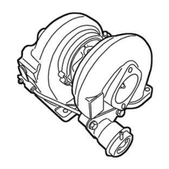
1. PARTS LIST 1.Turbocharger T517Z 8c ㎡ 1 P565 (Cast Ductile Iron) 1 2.Exhaust manifold (Cast Ductile Iron, 60φSteel) 1 3.Downpipe (THE31C) 1 4.Intercooler (60φ Aluminum) 1 5.Suction Pipe (60φ Aluminum) 1 6.TZ Suction Flange (50φ Aluminum) 1 7.Compression Pipe 〃... - Page 4 50φ×70mm Straight 5 34.Silicone Hose 〃 60φ×70mm Straight 1 〃 50φ-60φ Reducer 3 〃 60φ-65φ Reducer 1 〃 60φ-80φ Reducer 1 12φ ♯8 2 39.Hose band 〃 16φ ♯10 4 〃 50φ ♯32 13 〃 60φ ♯36 7 〃 65φ ♯40 1...
- Page 5 - 2 69.M6×10 P=1.0 Stainless (Down pipe Heatshield) - - 4 70.M6×15 P=1.0 Stainless (Oil Return・Heatshield) - 2 71.M6×15 P=1.0 Stainless (S-1,C-3 Bracket) - 3 72.M6×45 P=1.0 Stainless (ECM) - 1 73.M6 P=1.0 Stainless (Heatshield Bracket) - - - 1 74.M6...
- Page 6 1. PARTS LIST 1 2 3 4 5 6 7 8 9 10 11 12 13 14 15 16 17 18 19 20...
- Page 7 21 22,23 24 25 26 27 28 29 30~33 34,35 36~38 39~44 45 46 47 48 49 50 51 52...
- Page 8 53 54 55 56 57 58 59 60 61.62 63 64 65 66、67 68~82...
- Page 9 2. Removal of Stock Parts When removing the stock parts, make sure you read over the factory repair manual for proper procedures. 2-1 Remove the battery. 2-2 Release the fuel pressure in the fuel system. (see factory repair manual for detail procedure).
-
Page 10: Kit Installation
This installation should only be performed by a trained specialist who is very familiar with the automobile’s electrical and fuel management system. GReddy Performance Products Inc. is not responsible for any damage to the vehicle’s electrical system caused by improper installation. - Page 11 ・ ・ ・ ・ Make sure to use safety wire to wrap the thermo cloth. Zip ties will melt from the heat and eventually will come off. ・ ・ ・ ・ GReddy Performance Products, Inc. will not be responsible for any damage caused due to improper installation.
- Page 12 Oil Pressure Line Installation (1) Remove the Oil Pressure switch and install the union fitting and 3-way fitting on to the block. * Use Teflon tape on PT threads but not on the PF thread. (Parts used #21,22,23) (2) Install the oil pressure switch to the 3-way fitting.
- Page 13 Turbocharger Installation (1) Wrap the thermo cloth the actuator as shown. The heat off the manifold can damage the actuator with out the thermo cloth. • Use safety wire to secure the thermo cloth. (2) Install stud bolts on to the exhaust manifold, then mount the turbocharger to the manifold with compressor housing on the driver side.
- Page 14 (4) Install the Oil return hose bracket to the block and secure the hose to the bracket using provided zip ties as shown. (Parts used #61, 65) (5) Modify the drive shaft heat shield by cutting the shaded area in the picture to prevent the hose from rubbing up on the shield.
- Page 15 3-10 Horn Installation (4) Install the horn using provided aluminum Aluminum Spacer spacer as shown. (Parts used #66,77) 3-11 Compression Pipe Installation 5φ φ φ φ -1/8PT (1) Install Vacuum Fitting 5φ-1/8PT to the Compression pipe C-1. (Parts used #7,28) (2) Install Compression pipe C-1 to the outlet of the turbo using the provided gasket and hardware.
- Page 16 (4) Install compression pipe C-5~ C-8 between intercooler and throttle body. Using provided hose and clamps. (Parts used #11,12,13,14,34,36,37,41,42,43) Stock bolt 3-12 Airinx Installation (1) Remove the top bolt on the Airinx air filter and Main remove the outer frame, Install the provided hose adapter to the inner frame of the Airinx.
- Page 17 (7) Install the S-1. Secure the suction pipe bracket to the factory air cleaner box mounting point as shown. (Parts used #5,35,42,71) (8) Install the Airinx and the adapter to suction Pipe S-1 * Make sure that the Airinx and the piping does rub up on to the battery.
- Page 18 (3) Install the downpipe to the turbo using provided gasket and hardware. *Make sure that there is enough clearance between the downpipe and the oil pressure line. (Parts used #3,46,79,80) (4) Reinstall the catalytic converter and reconnect the o2 sensor connectors. *Reuse factory hardware to bolt the cat back on but the bolts with springs will require the provided nuts.
- Page 19 (2) Remove the injector clips off the rail, and remove the injectors. (3) Install the new injectors on to the rail. * Lube the o-rings on the injectors and make sure not to damage the o-ring when installing them in to the rail.
- Page 20 It is very important that you monitor the boost pressure, and make sure not to over boost. Over boosting can cause engine damage. GReddy Performance Products, Inc. is not responsible for any engine damage caused by over boosting (increased boost), modification to the kit, and/or misuse of the product.
- Page 21 e-manage Ultimate Information Important! The e-manage included in this kit is preprogrammed for this turbo kit. Do not attempt to adjust any of the settings in the e-manage. Any adjustments made can cause damage to the e-manage, engine and the factory ECU.
Need help?
Do you have a question about the Turbo Kit and is the answer not in the manual?
Questions and answers