Table of Contents
Advertisement
Quick Links
Advertisement
Table of Contents

Subscribe to Our Youtube Channel
Related Manuals for Goldmund SR2.3


Summary of Contents for Goldmund SR2.3
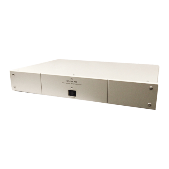
- Page 1 GOLDMUND SR2.3 2 CHANNEL POWER AMPLIFIER...
-
Page 2: User Manual
GOLDMUND SR2.3 2 CHANNEL AMPLIFIER USER MANUAL ATTENTION : No connection or manipulation must be done before reading those instructions. Damage to the amplifier may result if the following instructions are not consciously understood and applied. -
Page 3: Choice Of Amplifier Location And Cooling
2 - CHOICE OF AMPLIFIER LOCATION AND COOLING The GOLDMUND SR2.3 amplifier, as all the high quality amplifiers may generate a large amount of heat if driven into high power. It is mandatory to allow a proper cooling of the heat sink. Avoid any location which is not properly ventilated and avoid putting other equipment on top of the amplifier. - Page 4 5 – AMPLIFIER CONTROLS On the front plate of the GOLDMUND SR2.3 amplifier you will find only one switch : The POWER key, used to power the amp on and one power led. When turned ON the 2 channels are immediately connected and the front panel POWER led lights up.
-
Page 5: Sound Quality Optimization
Be patient… - Mains line phase inversion. The sonic quality of your GOLDMUND SR2.3 can be greatly improved if the mains AC line is properly connected. Try to invert the AC plugs of both your amplifiers, using special adapters. -
Page 6: Safety And Precautions
There is no risk to leave the speaker terminals unconnected when the amps are on. 8 - MAINTENANCE The GOLDMUND SR2.3 amplifier usually requires no maintenance. For the audio purists who want to keep their amp sounding as new, we only recommend that after a year or two, you have a technician or an official GOLDMUND representative readjust the DC offset. -
Page 7: Technical Data
TECHNICAL DATA POWER - Nominal power before clipping: 2x200 W RMS (2 - 8 Ohms). 150 W RMS (1 - 16 Ohms). - Maximum power : > 400 W RMS (3 Ohms). - Maximum voltage : 55 V peak. - Maximum current : > 15 A peak. These values for all channel driven FREQUENCY RESPONSE These figures are valid for the circuit alone, at any level between 0 and nominal power.
Need help?
Do you have a question about the SR2.3 and is the answer not in the manual?
Questions and answers