Table of Contents
Advertisement
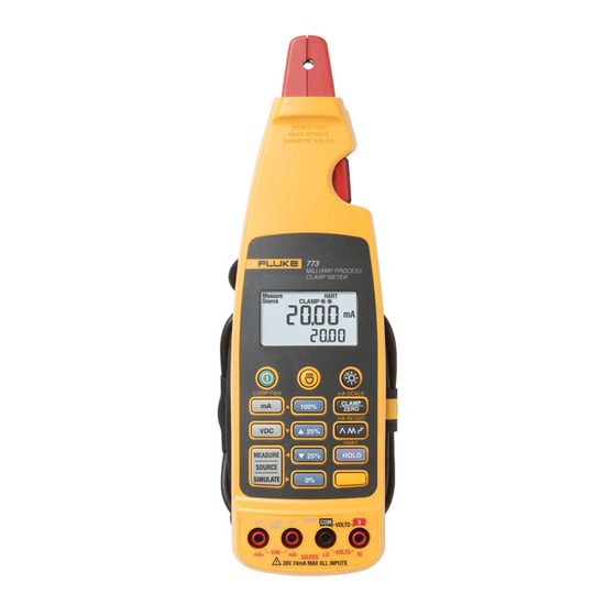
Milliamp Process Clamp Meter
Introduction
The hand-held, battery-operated Fluke 772/773/773-II Milliamp Process
Clamp Meters (the Meter or Product) can be used in troubleshooting
transmitters, valves, PLC and DCS I/O. Unlike conventional clamp meters,
the Meter features a remote jaw that is connected to the main body via
extension cable.
Features
•
In-circuit measurement of 0 mA to 24 mA dc and up to 99.9 mA dc
using a remotely connected clamp via extension cable
•
0 mA to 24 mA dc sourcing and simulating
•
0 V to 10 V dc sourcing (773/773-II)
•
Loop power supply 24 V dc output
•
0 V to 30 V dc measurement (773/773-II)
•
Scaled mA output (773/773-II)
•
Simultaneous mA measurement via detachable clamp and mA
sourcing (773/773-II)
•
250 Ω HART resistor for mA source
•
Electronic zero
•
Percentage span (0 % to 100 %)
•
Hold
•
Auto power off (battery saver)
•
Display backlight
•
Measurement spotlight LED
PN 3351049
February 2009 Rev. 2, 6/23
© 2009-2023 Fluke Corporation. All rights reserved.
All product names are trademarks of their respective companies. Specifications are subject to
change without notice.
772/773/773-II
Instruction Sheet
Advertisement
Table of Contents

Related Manuals for Fluke 773-II


Summary of Contents for Fluke 773-II
- Page 1 • 0 mA to 24 mA dc sourcing and simulating • 0 V to 10 V dc sourcing (773/773-II) • Loop power supply 24 V dc output • 0 V to 30 V dc measurement (773/773-II) •...
-
Page 2: Contacting Fluke
TL 940 mini hook test leads • Instruction sheet Contacting Fluke Fluke Corporation operates worldwide. For local contact information, go to our website: www.fluke.com To register your product, view, print, or download the latest manual or manual supplement, go to our website. - Page 3 • Comply with local and national safety codes. Use personal protective equipment (approved rubber gloves, face protection, and flame-resistant clothes) to prevent shock and arc blast injury where hazardous live conductors are exposed. • Do not touch voltages >30 V ac rms, 42 V ac peak, or 60 V dc.
- Page 4 The affixed label indicates that you must not discard this electrical/electronic product in domestic household waste. Do not dispose of this product as unsorted municipal waste. For information about take-back and recycling programs available in your country, see the Fluke website.
-
Page 5: Getting Acquainted With The Meter
Clamp mode. The Clamp modes includes clamp measure, mA scale output, and mA IN/OUT. Press N first to change to mA scale (773/773-II). Cycles through source output ramping and 25 % stepping: () Slow repeating 0 % - 100 % - 0 % ramp () Fast repeating 0 % - 100 % - 0 % ramp... - Page 6 fjv05.emf Number Description Detachable clamp Tactile Barrier docked and un-docked. Refer to Safety Information and Symbols. Display Measurement spotlight LED Figure 2. The Milliamp Process Clamp Meter...
- Page 7 Shift is active Reading is scaled Loop Power is active Milliamps Volts dc Percentage Secondary display Ramping is engaged Low battery symbol Maximum voltage warning High voltage is present Measure, Source, or Simulate is active Figure 3. Display (773/773-II shown)
-
Page 8: Zero Adjust
The Source and Simulate Percentage Span feature displays the span for 4 to 20 mA loops. Use G, F, E, and D to adjust the source or simulated current (772) or dc voltage and current (773/773-II). 20 mA 100 %... -
Page 9: User Options
User Options Several user options can be activated at Meter power up. Hold N when powering on the Meter. While holding down N, toggle on/off each option by repeatedly pressing the following keys: • Q toggle on/off backlight auto off. Display shows bLit on or oFF. •... -
Page 10: Probe Holder
Probe Holder The Meter is equipped with a probe holder that can either hold a test probe or can be used to attach the Fluke ToolPak. See Figure 5. Fjv08.emf Figure 5. The Probe Holder Taking Measurements XW Warning To prevent possible electric shock, fire, or personal injury, do not use the clamp on non-insulated conductors. - Page 11 Figure 7. Taking Measurements with the Test Leads Current and Voltage Output Functions Both Meters provide steady, stepped, and ramped current output for testing 0-24 mA current loops. Additionally, the 773/773-II provides voltage output to 10 V. To access these functions, press necessary.
- Page 12 Insert the test leads into the -mA and +mA jacks. Press L. Press until Source appears on the display. To enter mA Source mode for the 773/773-II, see Figure 8: Insert the test leads into the desired input jacks. Press L. until Source appears on the display.
- Page 13 Fjv11.emf Figure 9. Simulating mA Output Loop Supply In Loop Supply mode, the Meter powers a transmitter while measuring the mA signal. To enter Loop Supply mode, see Figure 10: Insert the test leads into the LOOP PWR jacks. See Figure 10. Press N.
-
Page 14: Maintenance
Maintenance XW Warning To prevent possible electric shock, fire, or personal injury: • Remove the input signals before you clean the Product. • Repairs or servicing not covered in this manual should be performed only by qualified personnel. • Replace all batteries with fresh batteries of the same manufacturer and type to prevent battery leakage. -
Page 15: Product Disposal
Range ..........0 mA to 24 mA Resolution........... 0.01 mA Accuracy ..........0.2 % + 2 counts Maximum Voltage ....... 50 V DC Voltage Measurement (773/773-II) Range ..........0 V to 30 V Resolution........... 0.01 V Accuracy ..........0.2 % + 2 counts DC voltage source (773/773-II) Range .......... -
Page 16: Mechanical Specifications
Measurement range ......0 mA to 24 mA Measurement resolution ..... 0.01 mA Measurement accuracy ...... 1 % FS Scaled mA current output to mA current input from the Jaw (773/773-II) Range ..........0 mA to 24 mA Resolution........... 0.01 mA Accuracy .......... -
Page 17: Miscellaneous Specifications
Electromagnetic Compatibility (EMC) International ..........IEC 61326-1: Portable Electromagnetic Environment IEC 61326-2-2 CISPR 11: Group 1, Class A Group 1: Equipment has intentionally generated and/or uses conductively-coupled radio frequency energy that is necessary for the internal function of the equipment itself. Class A: Equipment is suitable for use in all establishments other than domestic and those directly connected to a low voltage power supply network that supplies buildings used for domestic purposes. -
Page 18: User Replaceable Parts
The Fluke 772/773 will be free from defects in material and workmanship for 3 years (one year for cable and clamp) from the date of purchase. The 773-II will be free from defects in material and workmanship for 5 years (one year for cable and clamp) from the date of purchase.
Need help?
Do you have a question about the 773-II and is the answer not in the manual?
Questions and answers