Table of Contents
Advertisement
Quick Links
Advertisement
Table of Contents

Related Manuals for Fluke 789


Summary of Contents for Fluke 789
- Page 1 ProcessMeter™ Users Manual August 2002 Rev. 3, 3/13 © 2002-2013 Fluke Corporation, All rights reserved. Specifications are subject to change without notice. All product names are trademarks of their respective companies. Fluke-Direct .com info@Fluke-Direct.com 1.888.475.5235...
- Page 2 LIMITED WARRANTY AND LIMITATION OF LIABILITY This Fluke product will be free from defects in material and workmanship for three years from the date of purchase. This war- ranty does not cover fuses, disposable batteries, or damage from accident, neglect, misuse, alteration, contamination, or abnormal conditions of operation or handling.
-
Page 3: Table Of Contents
Table of Contents Title Page Introduction ........................1 How to Contact Fluke ..................... 1 Safety Information ......................2 How to Get Started ......................5 Getting Acquainted with the Meter ................. 6 Measuring Electrical Parameters ..................18 Input Impedance ......................18 Ranges ........................ - Page 4 Loop Power Supply Mode ....................29 Battery Life ........................31 Maintenance ........................31 General Maintenance..................... 31 Calibration ......................... 31 Replacing a Fuse ...................... 34 If the Meter does not Work ..................34 Replacement Parts and Accessories ................35 Specifications ......................... 39 Fluke-Direct .com info@Fluke-Direct.com 1.888.475.5235...
- Page 5 Pushbuttons .......................... 13 Display ........................... 16 mA Output Adjust Pushbuttons ..................... 25 mA Stepping Pushbuttons ..................... 26 mA Step Values ........................26 Power-Up Options ......................... 28 Typical Alkaline Battery Life ....................31 Replacement Parts ........................ 37 Fluke-Direct .com info@Fluke-Direct.com 1.888.475.5235...
- Page 6 List of Figures Figure Title Page Fluke 789 ProcessMeter ......................5 Input/Output Jacks......................... 6 Rotary Function Switch Positions for Measurements ............8 Rotary Function Switch Positions for mA Output ..............10 Pushbuttons .......................... 12 Elements of the Display ......................15 Sourcing Current ........................
-
Page 7: Introduction
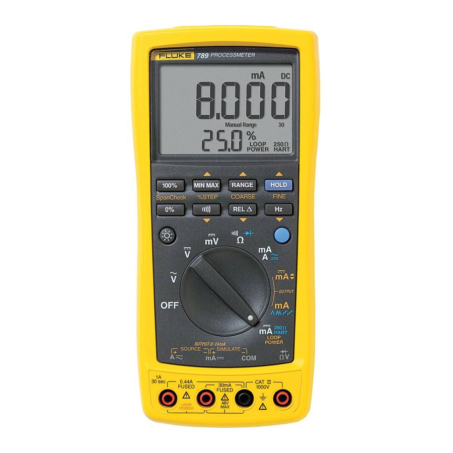
Warning Read “Safety Information” before using the meter. The Fluke 789 ProcessMeter (referred to as “the meter”) is a handheld, battery-operated tool for measuring electrical parameters, supplying steady or ramping current to test process instruments, and providing a > 24 V loop power supply. -
Page 8: Safety Information
Users Manual • To view, print, or download the latest manual supplement, Inspect the test leads for damaged insulation or visit http://us.fluke.com/usen/support/manuals. exposed metal. Check test lead continuity. Replace damaged test leads before using the Safety Information meter. • Do not use the meter if it operates abnormally. - Page 9 One exception is when the probe is used with the AC172 or AC175. • To avoid personal injury or damage to the meter, use only the specified replacement fuse, 440 mA 1000 V fast-blow, Fluke PN 943121. Fluke-Direct .com info@Fluke-Direct.com 1.888.475.5235...
-
Page 10: International Symbols
Category: With reference to the equipment types in the WEEE Directive Annex I, this product is classed as category 9 "Monitoring and Control Instrumentation" product. Do not dispose of this product as unsorted municipal waste. Go to Fluke’s website for recycling information. Fluke-Direct .com... -
Page 11: How To Get Started
ProcessMeter™ How to Get Started How to Get Started Display If familiar with the Fluke 80 Series DMM, read “Using the PROCESSMETER Current Output Functions,” review the tables and figures in “Getting Acquainted with the Meter,” and begin using the meter. -
Page 12: Getting Acquainted With The Meter
Figure 3 and Table 3 describe the input functions of • Figure 6 and Table 7 explain what all the elements of the first six rotary function switch positions. the display indicate. CAT IV 600 V anw001f.eps Figure 2. Input/Output Jacks Fluke-Direct .com info@Fluke-Direct.com 1.888.475.5235... -
Page 13: Input/Output Jacks
Input for voltage to 1000 V, Ω, continuity, and diode test. Common for all measurements. Common for transmitter simulation to 24 mA. (Use in series with an external loop supply.) Fluke-Direct .com info@Fluke-Direct.com 1.888.475.5235... -
Page 14: Rotary Function Switch Positions For Measurements
Users Manual HART LOOP POWER anw002f.eps Figure 3. Rotary Function Switch Positions for Measurements Fluke-Direct .com info@Fluke-Direct.com 1.888.475.5235... -
Page 15: Rotary Function Switch Positions For Measurements
High test lead in cA: Measure A dc Same as above, except there is only one range for each input jack position, 30 mA or 1 A J (Blue) selects ac High test lead in dmA: Measure mA Fluke-Direct .com info@Fluke-Direct.com 1.888.475.5235... -
Page 16: Rotary Function Switch Positions For Ma Output
Users Manual HART LOOP POWER anw008f.eps Figure 4. Rotary Function Switch Positions for mA Output Fluke-Direct .com info@Fluke-Direct.com 1.888.475.5235... -
Page 17: Rotary Function Switch Positions For Ma Output
Test leads in SOURCE: J (Blue) cycles through: HART LOOP POWER • 250 Ω series resistor for HART Supply > 24 V loop power, measure mA communication switched in • 250 Ω series resistor switched out Fluke-Direct .com info@Fluke-Direct.com 1.888.475.5235... -
Page 18: Pushbuttons
Users Manual 100% MIN MAX RANGE HOLD %STEP COARSE FINE SpanCheck anw003f.eps Figure 5. Pushbuttons Fluke-Direct .com info@Fluke-Direct.com 1.888.475.5235... -
Page 19: Pushbuttons
Measuring: Selects a fixed range (hold for 1 second for auto range) mA Output: Adjusts output up 0.1 mA COARSE Measuring: Toggles AutoHold, or in MIN MAX recording, suspends recording mA Output: Adjusts output up 0.001 mA FINE Fluke-Direct .com info@Fluke-Direct.com 1.888.475.5235... - Page 20 Measuring: Toggles relative reading (sets a relative zero point) mA Output: Adjusts output down 0.1 mA % STEP Measuring: Toggles between Ω measure and continuity functions mA Output: Adjusts mA output down to the next lower 25 % step Fluke-Direct .com info@Fluke-Direct.com 1.888.475.5235...
-
Page 21: Elements Of The Display
ProcessMeter™ Getting Acquainted with the Meter anw004f.eps Figure 6. Elements of the Display Fluke-Direct .com info@Fluke-Direct.com 1.888.475.5235... -
Page 22: Display
MAX - the display is showing the maximum-recorded value MIN - the display is showing the minimum-recorded value AVG - the display is showing the average value since starting recording (up to about 40 hours continuous recording time) Fluke-Direct .com info@Fluke-Direct.com 1.888.475.5235... - Page 23 - slow ramp in 25 % steps (15 seconds/step) p - fast ramp in 25 % steps (5 seconds/step) 250 Ω Lights when 250 Ω series resistance is switched in HART Lights when in loop supply mode Loop Power Fluke-Direct .com info@Fluke-Direct.com 1.888.475.5235...
-
Page 24: Measuring Electrical Parameters
If the range is too low, the display shows OL drop. (overload). Reverse the probes. The meter displays OL, • If the range is too high, the meter will not be indicating a high impedance. displaying its most precise measurement. Fluke-Direct .com info@Fluke-Direct.com 1.888.475.5235... -
Page 25: Displaying Minimum, Maximum, And Average
If MIN MAX recording is on continuously for over 40 hours, minimum and maximum readings are still recorded, but the displayed average no longer changes. In MIN MAX recording, press H to suspend recording; press H again to resume recording. Fluke-Direct .com info@Fluke-Direct.com 1.888.475.5235... -
Page 26: Compensating For Test Lead Resistance
The way to tell which mode is in use is to see output for testing 0-20 mA and 4-20 mA current loops. which pair of output jacks is in use. Choose source mode, in which the meter supplies the current, simulate mode, in which the meter regulates Fluke-Direct .com info@Fluke-Direct.com 1.888.475.5235... -
Page 27: Sourcing Current
ProcessMeter™ Using the Current Output Functions PROCESSMETER 100% MIN MAX RANGE HOLD SpanCheck %STEP COARSE FINE HART LOOP POWER CAT IV 600 V anw010f.eps Figure 7. Sourcing Current Fluke-Direct .com info@Fluke-Direct.com 1.888.475.5235... -
Page 28: Simulate Mode
Wait at least 2 seconds, then release R. The display looks the same in source and simulate modes. The way to tell which mode is in use is to see which pair of output jacks is in use. Fluke-Direct .com info@Fluke-Direct.com 1.888.475.5235... -
Page 29: Simulating A Transmitter
ProcessMeter™ Using the Current Output Functions dc V Power Supply PROCESSMETER +24V 100% MIN MAX RANGE HOLD COARSE FINE SpanCheck %STEP HART LOOP POWER CAT IV 600 V anw011f.eps Figure 8. Simulating a Transmitter Fluke-Direct .com info@Fluke-Direct.com 1.888.475.5235... -
Page 30: Producing A Steady Ma Output
The STEP pushbuttons described Table 9 are Select either sourcing or simulating by choosing the available when the meter is producing a steady SOURCE or SIMULATE output jacks. mA output. The STEP pushbuttons go to the next multiple of 25 %. Fluke-Direct .com info@Fluke-Direct.com 1.888.475.5235... -
Page 31: Manually Stepping The Ma Output
(-----) appear on the numeric display. When the impedance between the SOURCE jacks is low enough, the meter will resume sourcing. Note The COARSE and FINE adjustment pushbuttons described in Table 8 are available when manually stepping the mA output. Fluke-Direct .com info@Fluke-Direct.com 1.888.475.5235... -
Page 32: Auto Ramping The Ma Output
Auto ramping gives the ability to continuously apply a varying current stimulus from the meter to a transmitter, while hands remain free to test the response of the transmitter. Select either sourcing or simulating by choosing the SOURCE or SIMULATE jacks. Fluke-Direct .com info@Fluke-Direct.com 1.888.475.5235... -
Page 33: Power-Up Options
At any time during auto ramping, the ramp can be frozen simply by moving the rotary function switch to the [ mA position. Then the COARSE, FINE, and % STEP adjust pushbuttons can be used to make adjustments. Fluke-Direct .com info@Fluke-Direct.com 1.888.475.5235... -
Page 34: Power-Up Options
30 minutes of inactivity. Auto power off is disabled regardless of this option if MIN MAX recording is on. Display test/show firmware version Disabled Display HOLD (as long as button is pushed), then shows firmware version. Fluke-Direct .com info@Fluke-Direct.com 1.888.475.5235... -
Page 35: Loop Power Supply Mode
A jacks. The mA jack is the common and the A jack is at > 24 V dc. Connect the meter in series with the anw020f.eps Figure 9. Loop Power Voltage vs. Current instrument current loop as Figure 10 shows. Fluke-Direct .com info@Fluke-Direct.com 1.888.475.5235... -
Page 36: Connections For Supplying Loop Power
Users Manual PROCESSMETER 100% MIN MAX RANGE HOLD SpanCheck %STEP COARSE FINE TEST DC PWR – + – – HART LOOP POWER CAT IV 600 V Black anw009f.eps Figure 10. Connections for Supplying Loop Power Fluke-Direct .com info@Fluke-Direct.com 1.888.475.5235... -
Page 37: Battery Life
Avoid using the backlight. • Calibrate the meter once a year to ensure that it performs Do not disable the automatic power-off feature. according to its specifications. Contact a Fluke Service • Turn the meter off when not in use. Center for instructions. - Page 38 Close and latch the battery door before using the meter. Reinstall the battery door and tighten screws. Replace the batteries as follows. Refer to Figure 11. Use four AA alkaline batteries. Remove the test leads and turn the meter OFF. Fluke-Direct .com info@Fluke-Direct.com 1.888.475.5235...
-
Page 39: Replacing The Batteries And Fuses
ProcessMeter™ General Maintenance anw037.eps Figure 11. Replacing the Batteries and Fuses Fluke-Direct .com info@Fluke-Direct.com 1.888.475.5235... -
Page 40: Replacing A Fuse
OFF. meter, use only the specified replacement With a standard blade hand screwdriver, turn each fuse, 440 mA 1000 V fast-blow, Fluke PN battery door screw counterclockwise so that the slot 943121. is parallel with the screw picture molded into the Both current input jacks are fused with separate 440 mA case. -
Page 41: Replacement Parts And Accessories
ProcessMeter™ Replacement Parts and Accessories If the meter still does not work, contact a Fluke Service Replacement Parts and Accessories Center. If the meter is under warranty, it will be repaired ! Warning or replaced (at Fluke’s option) and returned at no charge. -
Page 42: Replacement Parts
Users Manual anw005f.eps Figure 12. Replacement Parts Fluke-Direct .com info@Fluke-Direct.com 1.888.475.5235... -
Page 43: Replacement Parts
ProcessMeter™ Replacement Parts and Accessories Table 13. Replacement Parts Reference Item Number Description Fluke PN or Model no. Quantity Designator MP14 Knob Assembly 658440 Top Case with Lens Protector 1622855 Decal, Top Case 1623923 Keypad 1622951 Top Shield... - Page 44 Users Manual Table 13. Replacement Parts (continued) Reference Item Number Description Fluke PN or Model no. Quantity Designator MP50 Shock Absorber 878983 MP11 Bottom Case 659042 MP20 Battery Contact, Negative 658382 BT1-4 Battery, 1.5 V, 0-15 mA, AA Alkaline 376756...
-
Page 45: Specifications
Input impedance: 10 M (nominal), < 100 pF Normal mode rejection ratio: > 60 dB at 50 Hz or 60 Hz Common mode rejection ratio: > 120 dB at dc, 50 Hz, or 60 Hz Overvoltage protection: 1000 V Fluke-Direct .com info@Fluke-Direct.com 1.888.475.5235... - Page 46 Ω Input impedance: 10 M (nominal), < 100 pF, ac-coupled Common mode rejection ratio: > 60 dB at dc, 50 Hz, or 60 Hz In an RF field of 3 V/m, add 0.25 % of range Fluke-Direct .com info@Fluke-Direct.com 1.888.475.5235...
- Page 47 0.2 % + 2 1.5 V/A Note: 440 mA continuous, 1 A 30 seconds maximum Overload protection: 440 mA, 1000 V fast-blow fuse In an RF field of 3 V/m, in 30.000 mA range, add 0.14 % of range Fluke-Direct .com info@Fluke-Direct.com 1.888.475.5235...
- Page 48 0.1 kΩ 600 nA 0.2 % + 1 4.000 MΩ 0.001 MΩ 220 nA 0.35 % + 3 40.00 MΩ 0.01 MΩ 22 nA 2.5 % + 3 Overload protection: 1000 V Open circuit voltage: <3.9 V Fluke-Direct .com info@Fluke-Direct.com 1.888.475.5235...
- Page 49 400 mV 150 mV (50 Hz to 5 kHz) 150 mV 40 V 400 V 40 V 40 V 1000 V 400 V 400 V *Usable 0.5 Hz to 20 kHz with reduced sensitivity. VHz max Fluke-Direct .com info@Fluke-Direct.com 1.888.475.5235...
- Page 50 Span .............. 0 mA or 4 mA to 20 mA, with overrange to 24 mA Accuracy ............0.05 % of span Loop voltage ..........24 V nominal, 48 V maximum, 15 V minimum Compliance voltage ........21 V for 24 V supply Burden voltage ..........<3 V Fluke-Direct .com info@Fluke-Direct.com 1.888.475.5235...
- Page 51 [1] This product meets requirements for industrial (Class A) electromagnetic wave equipment and the seller or user should take notice of it. This equipment is intended for use in business environments and not to be used in homes. Fluke-Direct .com info@Fluke-Direct.com...
Need help?
Do you have a question about the 789 and is the answer not in the manual?
Questions and answers