Table of Contents

Related Manuals for Fluke 12E


Summary of Contents for Fluke 12E
-
Page 1: Digital Multimeter
® Digital Multimeter Users Manual 3382138 October 2008 © 2008 Fluke Corporation. All rights reserved. Printed in China. Specifications are subject to change without notice. All product names are trademarks of their respective companies. - Page 2 LIMITED WARRANTY AND LIMITATION OF LIABILITY This Fluke product will be free from defects in material and workmanship for three years from the date of purchase. This war- ranty does not cover fuses, disposable batteries, or damage from accident, neglect, misuse, alteration, contamination, or abnormal conditions of operation or handling.
-
Page 3: Table Of Contents
Table of Contents Title Page Introduction ........................1 Safety Information ......................1 Safe Working Practices ....................1 Instrument Overview ...................... 4 Terminals........................4 Display........................4 Battery Saver ......................... 5 Making Measurements ....................5 Manual Ranging and Auto Ranging................5 Data Hold ........................5 Measuring AC and DC Voltage.................. - Page 4 Users Manual Testing the Fuses...................... 9 Replacing the Batteries and Fuses ................10 Service and Parts ......................10 General Specifications ....................11 Accuracy Specifications ....................12...
-
Page 5: Introduction
Use the Meter only as specified in this manual, otherwise the protection provided by the Meter may be impaired. The Fluke 12E Multimeter (hereafter referred to as “the Meter”) is a 4,000 count instrument. In this manual, a Warning identifies conditions and actions that pose hazards to the user. - Page 6 Users Manual Warnings and Precautions To avoid possible electric shock or personal injury, and to avoid possible damage to the Meter or to the equipment under test, comply with the following practices: Before using the Meter, inspect the case. Do not use the Meter if it is damaged. Look for cracks or missing plastic. Pay particular attention to the insulation around the connectors.
- Page 7 Multimeter Safe Working Practices Warnings and Precautions (Continued) Before measuring current, check the Meter’s fuses (see “Testing the Fuses”) and turn OFF power to the circuit before connecting the Meter to the circuit. Do not operate the Meter with the case (or part of the case) removed. ...
-
Page 8: Instrument Overview
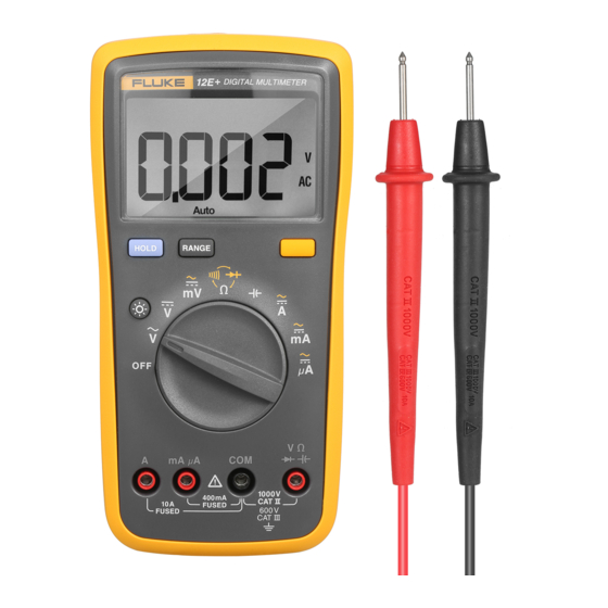
Users Manual Display Instrument Overview Terminals mA A 400mA CAT I 1000 V FUSED CAT II 600 V FUSED apg2f.eps Item Description apg1f.eps Relative mode is active Item Description Continuity selected Input terminal for ac and dc current Display Hold is enabled measurement to 10 A. -
Page 9: Battery Saver
Multimeter Battery Saver Warning Battery Saver Dangerous voltages may be present at the The Meter enters the “Sleep mode” and blanks the display input terminals and may not be displayed. if the Meter is not used and the input is inactive for 30 minutes. -
Page 10: Measuring Ac Or Dc Current
Users Manual Volts AC Volts DC Millivolts DC apg4f.eps apg3f.eps Figure 2. Measuring AC and DC Current Figure 1. Measuring AC and DC Voltage Measuring AC or DC Current Turn the rotary switch to Toggle between ac or dc current measurement by pressing the YELLOW button. -
Page 11: Measuring Resistance
Multimeter Making Measurements Measuring Resistance Warning To avoid electrical shock or damage to the <50 Meter when measuring resistance or continuity in a circuit, make sure the power to the circuit is turned off and all capacitors are discharged. ... -
Page 12: Testing Diodes
Users Manual Testing Diodes Measuring Capacitance Warning Caution To avoid electrical shock or damage to the To avoid damage to the Meter, disconnect Meter when testing diodes in a circuit, make circuit power and discharge all high-voltage sure the power to the circuit is turned off and capacitors before measuring capacitance. -
Page 13: General Maintenance
Multimeter Maintenance General Maintenance Testing the Fuses Warning Periodically wipe the case with a damp cloth and mild detergent. Do not use abrasives or solvents. To avoid electric shock or injury, remove the Dirt or moisture in the terminals can affect readings. test leads and any input signals before replacing the fuses. -
Page 14: Replacing The Batteries And Fuses
Meter correctly. Disconnect test leads before opening the To contact Fluke call: case or the battery door. +86-10-65123435 ext 15 in China www.fluke.com Visit Fluke’s Web site at apg6f.eps... -
Page 15: General Specifications
Multimeter General Specifications General Specifications Maximum Voltage between any Terminal and Earth Ground: 1000V Fuse Protection for mA μA inputs: 500 mA, 1000 V FAST, Min. Interrupt Rating 20,000 A Fuse Protection for A input: 10 A, 1000 V FAST, Min. Interrupt Rating 20,000 A Display: Digital: 4000 count updates 3/sec Operating: 0 °C to 40 °C,... -
Page 16: Accuracy Specifications
Users Manual Accuracy Specifications Accuracy is specified for 1 year after calibration, at operating temperatures of 18 °C to 28 °C, relative humidity at 0% to 75%. Accuracy specifications take the form of: ±([% of Reading] + [Number of Least Significant Digits]) Function Range Resolution... - Page 17 Multimeter Accuracy Specifications Function Range Resolution Accuracy 400.0 Ω 0.1 Ω 0.5% + 3 4.000 kΩ 0.001 kΩ 0.5% + 2 Resistance (Ohms) 40.00 kΩ 0.01 kΩ 0.5% + 2 400.0 kΩ 0.1 kΩ 0.5% + 2 4.000 MΩ 0.001 MΩ...
- Page 18 Users Manual Function Range Resolution Accuracy 40.00 mA 0.01 mA DC Current 1.5% + 3 400.0 mA 0.1 mA DC Current 4.000 A 0.01 A 1.5% + 3 10.00 A 0.01 A 4. When in the 4A range, display will show 4000 counts, please ignore the last digit. Overload Input Impedance Common Mode...
Need help?
Do you have a question about the 12E and is the answer not in the manual?
Questions and answers