Grizzly G0604 Owner's Manual
6" x 56" jointer
Hide thumbs
Also See for G0604:
- Owner's manual (68 pages) ,
- Manual (68 pages) ,
- Manual insert (59 pages)
Table of Contents
Advertisement
Quick Links
Advertisement
Table of Contents

Related Manuals for Grizzly G0604


Summary of Contents for Grizzly G0604
- Page 1 6" X 56" JOINTER OWNER'S MANUAL COPYRIGHT © JUNE, 2006 BY GRIZZLY INDUSTRIAL, INC. WARNING: NO PORTION OF THIS MANUAL MAY BE REPRODUCED IN ANY SHAPE OR FORM WITHOUT THE WRITTEN APPROVAL OF GRIZZLY INDUSTRIAL, INC. #TR8349 PRINTED IN CHINA.
- Page 2 ���� ������ �������� �������� ������ ������������ �� ��� ������ ������ ���������� ����������� ��� ������� �� ���� ������������������ ������� �� ����� ���������� ��� ������ ��� ������������ ����� �� ���� ������ ��� ������ �� ������� �������� ������� ��������� ����������� ������������� �� ������ ���...
-
Page 3: Table Of Contents
Table of Contents INTRODUCTION ..........................3 Foreword ............................ 3 Contact Info ..........................3 Machine Data Sheet ........................4 Identification ..........................5 SECTION 1: SAFETY........................6 Safety Instructions for Machinery ....................6 Additional Safety for Jointers ..................... 8 SECTION 2: CIRCUIT REQUIREMENTS ..................9 110V Operation .......................... - Page 4 SECTION 7: SERVICE ........................31 Troubleshooting Guide ......................31 Inspecting Knives ........................33 Adjusting/Replacing Knives ...................... 33 Checking/Adjusting Table Parallelism ..................36 Setting Outfeed Table Height ....................38 Setting Infeed Table ......................... 39 Calibrating Depth Scale ......................40 Setting Fence Stops ......................... 40 Wiring Diagram ........................
-
Page 5: Introduction
INTRODUCTION Foreword Contact Info We are proud to offer the Model G0604 6" X 56" If you have any comments regarding this manual, Jointer. This machine is part of a growing Grizzly please write to us at the address below: family of fine woodworking machinery. -
Page 6: Machine Data Sheet
Machine Data Sheet MACHINe dATA sHeeT Customer.Service.#:.(570).546-9663.•.To.Order.Call:.(800).523-4777.•.Fax.#:.(800).438-5901 Model G0604 6" X 56" Jointer Design Type:..................... Floor.Model Overall Dimensions: Table.Size....................6".W.x.55 ⁄ ".L Height.(from.floor.to.table)..................32 ⁄ " Table.Length......................55 ⁄ " Table.Width.........................6" Shipping.Weight....................347.lbs.. Net.Weight......................320.lbs. .Box.Size..................29"L.x.18"W.x.28"H .Box.Size..................62"L.x.21"W.x.14"H Stand.Footprint. -
Page 7: Identification
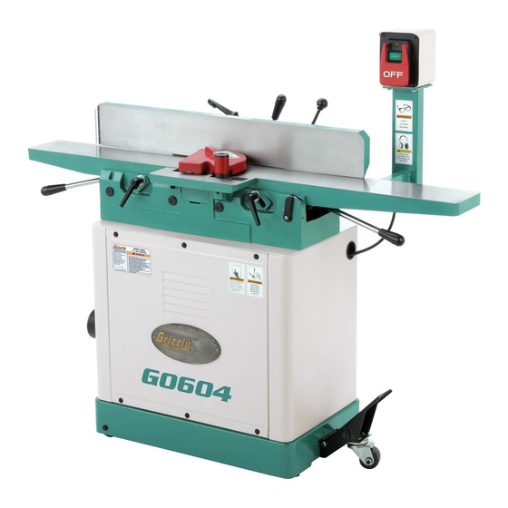
D. Fence Tilt Lock E. Cutterhead Guard Fence Tilt Handle G. Control Panel H. Infeed Table Infeed Table Adjustment Lever Mobile Base Lock K. Depth Scale Infeed Table Lock M. Outfeed Table Lock N. Outfeed Table Adjustment Lever G0604 6" X 56" Jointer... -
Page 8: Section 1: Safety
TIRED, OR UNDER THE INFLUENCE OF RESPIRATOR WHEN OPERATING DRUGS OR ALCOHOL. Be mentally alert MACHINERY THAT PRODUCES DUST. at all times when running machinery. Wood dust is a carcinogen and can cause cancer and severe respiratory illnesses. G0604 6" X 56" Jointer... - Page 9 Make sure you 16. MAKE SURE GUARDS ARE IN PLACE know what type of wood dust you will be AND WORK CORRECTLY BEFORE exposed to and always wear an approved USING MACHINERY. respirator. G0604 6" X 56" Jointer...
-
Page 10: Additional Safety For Jointers
No list of safety guidelines can be complete. Like all machines there is danger associ- Every shop environment is different. Always ated with the Model G0604. Accidents are frequently caused by lack of familiarity or consider safety first, as it applies to your individual working conditions. -
Page 11: Section 2: Circuit Requirements
DO NOT connect the machine to the power source until instructed to do so. Amperage Draw Electrocution or fire could The Model G0604 motor draws the following result if this machine is amps under maximum load: not grounded correctly or if your electrical con- Maximum Load ........ -
Page 12: Section 3: Setup
Rags for Cleaning ...... As Needed cess! Unpacking jointer assembly is very heavy. DO NOT The Model G0604 was carefully packed when it over-exert yourself while left our warehouse. If you discover the machine unpacking moving is damaged after you have signed for delivery, your machine—get assis-... -
Page 13: Inventory
• Cap Screws M10-1.5 x 30 (Carriage) ..2 missing. • Flat Washers 10mm (Carriage) ....2 • Cap Screws M6-1 x 20 (Ext Table) .... 2 -11- G0604 6" X 56" Jointer... -
Page 14: Hardware Recognition Chart
Hardware Recognition Chart -12- G0604 6" X 56" Jointer... -
Page 15: Cleanup
Consider the jointer dimensions and size of mate- rial to be processed through each machine, and space for auxiliary stands, work tables or other machinery when establishing a location for your jointer. See Figure 4 for the Model G0604 over- head view dimensions. ⁄ "... -
Page 16: Jointer
Figure 8). — If the pulleys are aligned, tighten the motor bracket fasteners and go to Step 8. — If the pulleys are NOT aligned, perform Figure 6. Securing jointer to stand. Steps 5–7. -14- G0604 6" X 56" Jointer... -
Page 17: Checking Outfeed Table Height
The belt guard MUST be installed before operating the jointer or the moving V-belt will be exposed, creating an entanglement hazard at the back of the jointer. Belt Guard Figure 9. Installing belt guard. -15- G0604 6" X 56" Jointer... -
Page 18: Extension Table
Figure 11. Using a straightedge to align outfeed table height with knife at TDC. Figure 12. Installing extension table. Use the straightedge to adjust the extension table flush with the infeed table. Tighten the cap screws. -16- G0604 6" X 56" Jointer... -
Page 19: Fence
Note: The paper will keep the carriage from making direct contact with the table, which will keep the fence from dragging across the table when it is installed. Figure 16. Installing the fence tilt lever. -17- G0604 6" X 56" Jointer... -
Page 20: Cutterhead Guard
—If the guard does not spring back over the cutterhead or drags across the table, rein- stall it, making sure there is tension on the shaft when it is installed, so it will spring back over the fence. -18- G0604 6" X 56" Jointer... -
Page 21: Knife Setting Jig
Assemble the knife setting jig as shown in Figure Figure 20. Installing dust port. Figure 19. Knife setting jig assembly. DO NOT operate the Model G0604 with- out an adequate dust collection system. This machine creates substantial amounts of wood dust while operating. Failure to use a dust collection system can result in short and long-term respiratory illness. -
Page 22: Test Run
— Immediately stop the jointer if you suspect any problems, and refer to Page 31 to troubleshoot/fix any problems before start- ing the jointer again. — If you need any help with your jointer call our Tech Support at (570) 546-9663. -20- G0604 6" X 56" Jointer... -
Page 23: Section 4: Operations
OMMEND that you read books, trade maga- zines, or get formal training before begin- Figure 22. Table control locations. ning any projects. Regardless of the con- tent in this section, Grizzly Industrial will not be held liable for accidents caused by lack of training. -21-... -
Page 24: Stock Inspection And Requirements
Tilt well as tear-out on the workpiece. Lock Plunger ������� ���� ����� Positive Stop ��������� Figure 24. Tilt lock and plunger locations. ������� ����� Figure 25. Correct and incorrect grain align- ment with cutterhead. -22- G0604 6" X 56" Jointer... -
Page 25: Squaring Stock
4. Rip Cut On A Table Saw—The jointed edge of the workpiece is placed against a table saw ⁄ " Min. fence and the opposite edge cut off. 1" Min. Figure 27. Minimum dimensions for surface Previously planing. Jointed Edge -23- G0604 6" X 56" Jointer... -
Page 26: Surface Planing
To keep your hands safe, DO NOT let them get closer than 4" from the cutterhead when it is moving! Repeat Step 7 until the entire surface is flat. Figure 29. Illustration of surface planing results. -24- G0604 6" X 56" Jointer... -
Page 27: Edge Jointing
DO NOT let them get closer than 4" from the cutterhead when it is mov- ing! Repeat Step 7 until the entire edge is flat. Figure 31. Illustration of edge jointing results. -25- G0604 6" X 56" Jointer... -
Page 28: Bevel Cutting
32 & 33). for dangerous conditions as described in the Stock Inspection instructions, beginning on The Model G0604 has preset fence stops at 45˚ Page 22. inward, 90˚, and 45˚ outward (135˚). If your situ- ation requires a different angle, the fence can be Set the cutting depth for your operation. -
Page 29: Section 5: Accessories
Comes with 5 extra replacement inserts. Very nice upgrade! Figure 37. G3631 Jointer/Planer Knife Hone. Figure 35. H9218 Byrd Shelix Cutterhead. -27- G0604 6" X 56" Jointer... - Page 30 Very simple and super fast knife changes! Figure 41. Straightedges. Figure 39. Dispoz-A-Blade Holder and Knife. ® -28- G0604 6" X 56" Jointer...
- Page 31 Features stainless steel, shock resistant construc- to wearing—at an affordable price! tion and a dust proof display. An absolute treat for the perfectionist! Figure 43. H6175 Power Respirator. Figure 45. Grizzly Dial Calipers. ® -29- G0604 6" X 56" Jointer...
-
Page 32: Section 6: Maintenance
SECTION 6: MAINTENANCE Cleaning Always disconnect power to the machine before Cleaning the Model G0604 is relatively easy. performing maintenance. Vacuum excess wood chips and sawdust, and Failure to do this may wipe off the remaining dust with a dry cloth. If any... -
Page 33: Section 7: Service
3. Replace V-belt (Page 14). 3. V-belt is damaged. Vibration when running 1. Loose or damaged blade. 1. Tighten or replace blade. or cutting. 2. Damaged V-belt. 2. Replace. 3. Worn cutterhead bearings. 3. Check/replace cutterhead bearings. -31- G0604 6" X 56" Jointer... - Page 34 (Page 36). tent difficulty feeding b. Set the knives (Page 33). workpiece. c. Set the outfeed table height to the knives (Page 38). d. Calibrate the fence stops (Page 40). -32- G0604 6" X 56" Jointer...
-
Page 35: Inspecting Knives
—If the knives do not touch the straightedge or they lift it up in any of the positions, then those knives need to be adjusted. -33- G0604 6" X 56" Jointer... - Page 36 Decide which adjustment The Model G0604 comes with both jack screws option you are going to use between the and springs inside the cutterhead to provide two jack screws and the springs.
- Page 37 Tighten the gib bolts just tight enough to hold the knife in place. Repeat on the other side of the cutterhead, then repeat Steps 5–7 with the rest of the knives. -35- G0604 6" X 56" Jointer...
-
Page 38: Checking/Adjusting Table Parallelism
Correct the outfeed table parallelism, then correct the infeed table parallelism. -36- G0604 6" X 56" Jointer... -
Page 39: Adjusting Table Parallelism
—If the straightedge does not sit flat against outfeed table, and loosen the set screws both the infeed and outfeed table in any underneath those removed set screws. of the positions, then follow the Adjusting Table Parallelism instructions. -37- G0604 6" X 56" Jointer... -
Page 40: Setting Outfeed Table Height
Set the knives (refer to Page 33), set the outfeed table height (refer to the next sub- section), and recalibrate the fence stops (Page 40). 10. Reinstall the cutterhead guard. -38- G0604 6" X 56" Jointer... -
Page 41: Setting Infeed Table
0.062" ⁄ ") above the cutterhead body, as deter- The infeed table on the Model G0604 has mined by using the feeler gauge or combina- positive stop bolts that, when properly set up, tion of feeler gauges (see Figure 57). -
Page 42: Calibrating Depth Scale
Adjust the positive stop bolt until the fence is exactly 45° inward while resting on the bolt (verify the angle with a 45° square). Figure 60. Depth scale adjusted to “0” position. Retighten the jam nut loosened in Step 2. -40- G0604 6" X 56" Jointer... - Page 43 Adjust the 45˚ outward positive stop bolt until the fence is exactly 45° outward while rest- ing on the bolt (check the angle with a sliding bevel set to 135°). Retighten the jam nut loosened in Step 2. -41- G0604 6" X 56" Jointer...
-
Page 44: Wiring Diagram
� ������ ������� ���� ������� �������� � � � � ������ ����� ������� ������ ���������� ����� ������ ������� �� ������� Electrical Components to Power Source Motor Junction Box Switch to Motor G0604 Wiring Diagram -42- G0604 6" X 56" Jointer... -
Page 45: Jointer Parts Breakdown
�� �� �� �� ��� �� �� ��� ��� �� �� ��� �� ��� �� �� ��� �� ��� �� ��� �� ��� �� �� ��� ��� ��� �� ��� �� ��� �� ��� -43- G0604 6" X 56" Jointer... -
Page 46: Jointer Parts List
ROLL PIN 3 X 16 P0604038 LOCK P0604079 SUPPORT PSS14M SET SCREW M8-1.25 X 12 P0604080 TABLE LIP P0604040 CLAMP PW02M FLAT WASHER 5MM P0604041 CLAMP PSB24M CAP SCREW M5-.8 X 16 P0604042 SCALE P0604083 TABLE LH -44- G0604 6" X 56" Jointer... - Page 47 SWITCH BOX PFH07M FLAT HD SCR M5-.8 X 10 P0604136 SWITCH ASSEMBLY' P0604110 PIVOT BRACKET PHTEK4M TAP SCREW M4 X 8 P0604111 ADJUSTING BLOCK P0604138 SWITCH BRACKET PN09M HEX NUT M12-1.75 P0604139 STRAIN RELIEF -45- G0604 6" X 56" Jointer...
-
Page 48: Stand/Motor Parts Breakdown
��� ��� ��� ��� ��� ��� ��� ��� ��� ��� ��� ��� ��� ��� ��� ��� ��� ��� ��� ��� ��� ��� ��� ��� ��� ��� ��� ��� ��� ��� ��� ��� ��� ��� -46- G0604 6" X 56" Jointer... -
Page 49: Stand/Motor Parts List
P0604225 MOTOR PULLEY PN02M HEX NUT M10-1.5 PSS02M SET SCREW M6-1 X 6 PB144M HEX BOLT M10-1.5 X 55 PK12M KEY 5 X 5 X 30 P0604261 PEDAL BRACKET P0604228 MOTOR 1HP P0604262 PEDAL -47- G0604 6" X 56" Jointer... -
Page 50: Warning Label Parts List
MUST maintain the original location and readability of the labels on the machine. If any label is removed or becomes unreadable, REPLACE that label before using the machine again. Contact Grizzly at (800) 523-4777 or www.grizzly.com to order new labels. -48- G0604 6" X 56" Jointer... -
Page 51: Warranty And Returns
WARRANTY AND RETURNS Grizzly Industrial, Inc. warrants every product it sells for a period of 1 year to the original purchaser from the date of purchase. This warranty does not apply to defects due directly or indirectly to misuse, abuse, negligence, accidents, repairs or alterations or lack of maintenance. - Page 52 -50- G0604 6" X 56" Jointer...
- Page 53 Do you think your machine represents a good value? _____ Yes _____No Would you recommend Grizzly Industrial to a friend? _____ Yes _____No Would you allow us to use your name as a reference for Grizzly customers in your area? Note: We never use names more than 3 times.
- Page 54 FOLD ALONG DOTTED LINE Place Stamp Here GRIZZLY INDUSTRIAL, INC. P.O. BOX 2069 BELLINGHAM, WA 98227-2069 FOLD ALONG DOTTED LINE Send a Grizzly Catalog to a friend: Name_______________________________ Street_______________________________ City______________State______Zip______ TAPE ALONG EDGES--PLEASE DO NOT STAPLE...
- Page 56 Buy Direct and Save with Grizzly – Trusted, Proven and a Great Value! ® Visit Our Website Today And Discover Why Grizzly Is The Industry Leader! ® • SECURE ORDERING • ORDERS SHIPPED WITHIN 24 HOURS • E-MAIL RESPONSE WITHIN ONE HOUR -OR- FREE Call Today For A...
Need help?
Do you have a question about the G0604 and is the answer not in the manual?
Questions and answers