
Related Manuals for Eiki LC-WGC500


Summary of Contents for Eiki LC-WGC500
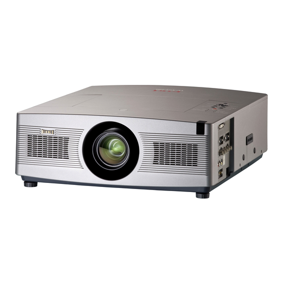
- Page 1 MULTIMEDIA PROJECTOR LC-WGC500 MODEL LC-WGC500L ✽ Projection lens is optional. ✽ OWNER’S MANUAL...
-
Page 2: Features And Design
Features and Design Functionally Rich Multilanguage Menu Display ◆ ◆ This projector has many useful functions such as lens Operation menu is available in 12 languages; English, shifting, ceiling and rear projection, perpendicular German, French, Italian, Spanish, Portuguese, Dutch, omnidirectional projection, variety of lens options, Swedish, Russian, Chinese, Korean, and Japanese etc. -
Page 3: Table Of Contents
Table of Contents Features and Design . . . . . . . . . . . . . . . . 2 Input Selection . . . . . . . . . . . . . . . . . . . 34 Table of Contents . -
Page 4: To The Owner
To the Owner Safety Precaution Before installing and operating the projector, read this WARNING: lTHIS APPARATUS MUST BE EARTHED manual thoroughly. lTO REDUCE THE RISK OF FIRE OR ELECTRIC SHOCK, The projector provides many convenient features and DO NOT EXPOSE THIS APPLIANCE TO RAIN OR functions. -
Page 5: Safety Instructions
Safety Instructions All the safety and operating instructions should be read Do not install the projector near the ventilation duct of air- before the product is operated. conditioning equipment. Read all of the instructions given here and retain them This projector should be operated only from the type for later use. -
Page 6: Air Circulation
Safety Instructions Air Circulation IMPORTANT! Filter Maintenance!! Openings in the cabinet are provided for ventilation. To ensure reliable operation of the product and to The projector uses a lamp which generates protect it from overheating, these openings must not significant heat. The cooling fans and air vents are be blocked or covered. -
Page 7: Installing The Projector In Proper Directions
Safety Instructions Installing the Projector in Proper Directions Use the projector properly in specified positions. Improper positioning may reduce the lamp life and result in severe accident or fire hazard. This projector can project the picture in upward, downward, or inclined position in perpendicular direction to the horizontal plane. -
Page 8: Moving The Projector
Safety Instructions Moving the Projector Use the hand grip when moving the projector. Replace the lens cap and retract the adjustable feet to prevent damage to the lens and cabinet when carrying. When the projector is not in use for an extended period, put it into a suitable case to protect the projector. -
Page 9: Compliance
Model Number(s) : LC-WGC500 , LC-WGC500L Trade Name : EIKI EIKI International, Inc. Responsible party 30251 Esperanza Rancho Santa Margarita CA 92688-2132 U.S.A. Address 800-242-3454 (949-457-0200) Telephone No. -
Page 10: Part Names And Functions
Part Names and Functions q Lens Release Button Front w Infrared Remote Receiver (Top&Front) e Terminals and Connectors r Top Controls and Indicators t Lens Cap (for LC-WGC500) y Speaker u Projection Lens (for LC-WGC500) i Adjustable Feet o Power Cord Connector !0 Optional Parts Attachment CAUTION Do not turn on the projector with the lens ✽... -
Page 11: Side Terminal
Part Names and Functions Side Terminal q HDMI TERMINAL y AUDIO 2 JACK Connect the HDMI signal (including sound signal) Connect the audio output (stereo) signal from a from video equipment or the DVI signal from computer or video equipment connected to i to computer to this terminal (p.20). - Page 12 Part Names and Functions Side Terminal !0 USB CONNECTOR (Series B) Use this connector when controlling a computer with the remote control of the projector. Connect the USB terminal of your computer to this connector with the supplied USB cable (p.20). !1 R/C JACK When using the wired remote control, connect the wired remote control to this jack with a remote...
-
Page 13: Top Control
Part Names and Functions Top Control q WARNING TEMP . indicator i SELECT button – Lights red light when the projector detects an abnormal –Execute the selected item (p.26). condition or the filter cartridge is not installed. – Expand or compress the image in the Digital zoom Blinks red when the internal temperature of the mode (p.47). -
Page 14: Remote Control
Part Names and Functions Remote Control q STAND-By button ed 7 8 ( VOLUME + / – ) buttons o POINT Turn the projector off (p.25). – Select an item or adjust the value in the On- Screen Menu (p.26). w WIRED REMOTE jack –... - Page 15 Part Names and Functions Remote Control For PIN code and remote control code. !3 MENU button @2 R ESET/ON/ALL-OFF switch Open or close the On-Screen Menu (p.26). When using the remote control, set this switch to “ON. ” Set it to “ALL OFF” for power saving when !4 P-TIMER button it is not in use.
-
Page 16: Remote Control Battery Installation
Part Names and Functions Remote Control Battery Installation Open the battery Install new batteries Replace the compartment lid. into the compartment. compartment lid. Press the lid Two AAA size batteries downward and slide it. For correct polarity (+ and –), be sure battery terminals are in contact with pins in the compartment. -
Page 17: Remote Control Code
Part Names and Functions Remote Control Code The eight different remote control codes (Code 1–Code 8) are assigned to this projector. Switching the remote control codes prevents interference from other remote controls when several projectors or video equipment next to each other are operated at the same time. Change the remote control code for the projector first before changing that for the remote control. -
Page 18: Installation
Installation Positioning the Projector (for LC-WGC500) For projector positioning, see the figures below. The projector should be set perpendicularly to the plane of the screen. ✔ Notes: • The brightness in the room has a great influence on picture quality. It is recommended to limit ambient lighting in order to obtain the best image. -
Page 19: Lens Installation
Installation Lens Installation When replacing the lens or using an optional lens, install the lens by following the instructions below. Ask the sales dealer for detailed information of the optional lens specifications. Lens Release button Removing the lens Shift the lens to the center position by using the Lens shift function (see page 28). -
Page 20: Connecting To A Computer (Digital And Analog Rgb)
Installation Connecting to a Computer (Digital and Analog RGB) Cables used for connection =Cables are not supplied with this projector.) • VGA Cable (Mini D-sub 15 pin) (One cable is supplied)* • HDMI-DVI Cable * • Serial Control Cable * •... -
Page 21: Connecting To Video Equipment (Video, S-Video, Component, Hdmi And Rgb Scart)
Installation Connecting to Video Equipment (Video, S-video, Component, HDMI and RGB Scart) Cables used for connection • Video Cable (RCA x 1) • VGA-Scart Cable • S-VIDEO Cable • BNC Cable • HDMI Cable (Cables are not supplied with the projector.) Component Video Composite Composite... -
Page 22: Connecting For Audio Signal
Installation Connecting for Audio Signal MONITOR OUT and AUDIO OUT Specifications Cables used for connection Selected MONITOR OUT AUDIO OUT • Audio Cable (Mini Plug [stereo] x 2) Input Terminal Terminal • Audio Cable (RCA x 2) Input 1 Input 1(D-Sub) Input 1 (Cables are not supplied with the projector.) Input 2... -
Page 23: Connecting The Ac Power Cord
Installation Connecting the AC Power Cord This projector uses nominal input voltages of 100–120 V or 200–240 V AC and it automatically selects the correct input voltage. It is designed to work with single-phase power systems having a grounded neutral conductor. To reduce the risk of electrical shock, do not plug into any other type of power system. -
Page 24: Basic Operation
Basic Operation Turning On the Projector Complete peripheral connections (with a computer, VCR, etc.) before turning on the projector. Connect the projector’s AC power cord into an AC outlet. The POWER indicator lights red. Press the ON/STAND-BY button on the top control or the ON button on the remote control. -
Page 25: Turning Off The Projector
Basic Operation Turning Off the Projector Press the ON/STAND-BY button on the top control or the STAND-BY button on the remote control, and “Power off?” appears on the screen. Press the ON/STAND-BY button or the STAND-BY button on the remote control again to turn off the projector. -
Page 26: How To Operate The On-Screen Menu
Basic Operation How to Operate the On-Screen Menu The projector can be adjusted or set via the On-Screen Top Control Menu. For each adjustment and setting procedure, refer to the respective sections in this manual. MENU button Press the MENU button on the top control or the remote control to display the On-Screen Menu. -
Page 27: Menu Bar
Basic Operation Menu Bar For detailed functions of each menu, see “Menu Tree” on pages 71-72. The menu bar displays changes depending on the input signals. Guide Window System [PC Adjust] Image Adjust Setting Menu Show the selected Select a Adjust Adjust the picture Set the projector’s... -
Page 28: Operating With Projector Control
Basic Operation Operating with Projector Control Lens Operation Top Control The following lens operation can be made with the Lens SHUTTER button on the top control. button Press the Lens button to enter each lens operation mode. LENS MENU The selected adjustment display appears on the screen. button button Zoom ➜... -
Page 29: Sound Adjustment
Basic Operation Sound Adjustment Direct Operation Top Control VOLUME +/– buttons Volume Press the VOLUME+/– buttons on the top control or on the remote control to adjust the volume. The volume dialog box appears on the screen for a few seconds. Mute Press the MUTE button on the remote control to temporarily Remote Control... -
Page 30: Operating With Remote Control
Basic Operation Operating with Remote Control Using the remote control for some frequently used operations is advisable. Just pressing one of the buttons enables you to make the desired operation quickly without calling up the On-Screen Menu. Remote Control FREEZE button Press the FREEZE button on the remote control to freeze the picture on the screen. -
Page 31: Pip Button
Basic Operation PIP button Remote Control Press the PIP button on the remote control to select Picture in Picture or Picture by Picture mode. See page 52 for details. P-TIMER button KEySTONE button PIP VOL . button PIP button SHUTTER Press the PIP VOL. -
Page 32: Laser Pointer Function
Basic Operation Laser Pointer Function This remote control emits a laser beam from the laser light window. Press the LASER button to activate the laser pointer. The signal emission indicator lights red and the red laser beam is emitted. If the LASER button is pressed for more than one minute or if it is released, the laser light goes off. -
Page 33: Wireless Mouse Operation
Basic Operation Wireless Mouse Operation The remote control can be used as a wireless mouse for your computer. Before operating the wireless mouse, connect your computer and the projector with the supplied USB cable (p. 20). When the Pointer function is used, the wireless mouse is not available. -
Page 34: Input Selection
Input Selection Input Remote Control Remote Control button operation INPUT 1 button Input 1 INPUT buttons RGB (PC analog) RGB (Scart) HDMI Remote Control Operation Press the INPUT 1, INPUT 2, or INPUT 3 buttons on the remote control. The input source appears on the screen as you press each button. -
Page 35: Input Source Selection
Input Selection Input Source Selection Menu Operation Input Menu Press the MENU button to display the On-Screen Menu. Use the Point buttons to move the red frame pointer to the Input Menu icon. Use the Point buttons to move the red arrow pointer to the desired input and then press the SELECT button. -
Page 36: Video System Selection
Input Selection Video System Selection Press the MENU button to display the On-Screen AV System Menu (Video or S-video) Menu. Use the Point buttons to move the red frame pointer to the AV System Menu icon. Use the Point buttons to move the red arrow AV System Menu icon pointer to the desired system and then press the The selected system is... -
Page 37: Computer Adjustment
Computer Adjustment Computer System Selection This projector automatically tunes to various types of computers based on VGA, SVGA, XGA, SXGA, WXGA, UXGA or WUXGA with its Multi-scan system and Auto PC Adjustment. If a computer is selected as a signal source, this projector automatically detects the signal format and tunes to project a proper image without any additional settings. -
Page 38: Auto Pc Adjustment
Computer Adjustment Auto PC Adjustment Auto PC Adjustment function is provided to automatically adjust Fine sync, Total dots, Horizontal and Vertical positions to conform to your computer. Direct Operation Remote Control The Auto PC adjustment function can be operated directly by pressing the AUTO PC button on the remote control. -
Page 39: Manual Pc Adjustment
Computer Adjustment Manual PC Adjustment Some computers employ special signal formats which may not be tuned by Multi-scan system of this projector. Manual PC Adjustment enables you to precisely adjust several parameters to match those signal formats. The projector has 10 independent memory areas to store those parameters manually adjusted. It allows you to recall the setting for a specific computer. - Page 40 Computer Adjustment Display area H Use the Point buttons to adjust the horizontal area displayed by this projector. Display area V Use the Point buttons to adjust the vertical area displayed by this projector. Reset Move the red frame pointer to To reset the adjusted data, select Reset and press the the desired item and press the SELECT button.
-
Page 41: Image Level Selection
Image Level Selection Image Level Selection Press the MENU button to display the On-Screen Image Menu icon Image Menu Menu. Use the Point buttons to move the red frame pointer to the Image Menu icon. Use the Point buttons to move the red frame pointer to the desired image level and then press the Move the red frame pointer SELECT button. -
Page 42: Image Adjustment
Image Adjustment Image Adjustment Press the MENU button to display the On-Screen *The figure below shows for video signal input. Menu. Use the Point buttons to move the red Image Adjust Menu frame pointer to the Image Adjust Menu icon. Use the Point buttons to move the red frame pointer to the desired item and then press the SELECT... - Page 43 Image Adjustment Sharpness Press the Point button to decrease the sharpness of the image; press the Point button to increase the sharpness of the image (from 0 to 15). Gamma Use the Point buttons to adjust the gamma value to obtain a better balance of contrast (from 0 to 15).
- Page 44 Image Adjustment Reset To reset the adjusted data, select Reset and press the Image Level Menu SELECT button. A confirmation box appears and then select Move the red frame [Yes]. All adjustments will return to their previous figures. pointer to an image item to be set and Store then press the...
-
Page 45: Screen Adjustment
Screen Adjustment Screen Adjustment Press the MENU button to display the On-Screen Screen Menu Menu. Use the Point buttons to move the red frame pointer to the Screen Menu icon. Use the Point buttons to move the red frame Screen Menu icon pointer to the desired function and then press the SELECT button. -
Page 46: Screen Size Adjustment (Computer Signals)
Screen Adjustment Screen Size Adjustment (Computer Signals) Select the desired screen size that conforms to the input signal source. Screen Menu Normal Provide the image to fit the screen size. Screen Menu icon True Move the red frame pointer Provide the image in its original size. When the original to the desired function and image size is larger than the screen size (1024 x 768), the press the SELECT button. - Page 47 Screen Adjustment For zooming in and out the images ✔ Notes: Digital zoom + • The projector cannot display any Select Digital zoom +. The On-Screen Menu disappears and resolution higher than 1600 x 1200. If “D. zoom +”appears. Press the SELECT button to expand your computer’s screen resolution is the image size.
-
Page 48: Screen Size Adjustment (Video, Component Signals)
Screen Adjustment Screen Size Adjustment (Video, Component Signals) Press the MENU button to display the On-Screen Screen Menu Menu. Use the Point buttons to move the red frame pointer to the Screen Menu icon. Use the Point buttons to move the red frame Screen Menu icon pointer to the desired function and then press the SELECT button. -
Page 49: Setting
Setting Setting This projector has a Setting menu that allows you to set up Setting Menu (Language) the other various functions described below. Press the MENU button to display the On-Screen Setting Menu icon Menu. Use the Point buttons to move the red frame pointer to the Setting Menu icon. - Page 50 Setting Capture Capture This function enables you to capture an image being projected to use it for a starting-up display or interval of presentations. Select Capture and press the SELECT button. A confirmation box appears and select [Yes] to capture the projected image.
- Page 51 Setting Enter a Logo PIN code Use the Point ed buttons on the top control or Number Enter a Logo PIN code buttons on the remote control to enter a number. When using top control Use the Point ed buttons on the top control to select a number.
- Page 52 Setting Picture in Picture This function is used to project two videos simultaneously by placing a separate small sub screen within the main screen. Use the Point ed buttons to move the red frame pointer to Picture in Picture and then press the SELECT button to display a dialog box.
- Page 53 Setting Lamp mode This Projector is equipped with 2 Projection Lamps. This function allows you to choose how to use the lamp as follows. Set the red frame pointer Lamp1.... Always use Lamp 1. to the item and press the SELECT button.
- Page 54 Setting Lamp control Lamp control This function allows you to change brightness of the screen. Auto 1 ..The brightness according to the input signal (between Normal and Eco mode). Auto 2 ..The brightness according to the input signal (between High and Eco mode). High ....
- Page 55 Setting Pointer Pointer You can emphasize a part of the projected image with this function. Use the Point buttons to choose either Spotlight or Pointer and press the SELECT button. Then use the Point buttons to select a size of the Spotlight (Large, Middle, or Small) or a pattern of the Pointer (Arrow, Finger, or Dot).
- Page 56 Setting Display Display This function decides whether to display On-Screen Displays. On ......Show all the On-Screen displays. Use this function when you want to project Use the Point buttons to images after the lamp becomes bright switch between the options. enough.
-
Page 57: Power Management
Setting Power management Select one of the following options: Ready ....When the lamp has been fully cooled down, the POWER indicator changes to fast blinking. In this condition, the projection lamp can be turned on if the input signal is reconnected or any button on the top control or remote control is pressed. - Page 58 Setting Shutter Shutter function is available to block out light to the screen, so that the screen can be used for the other presenters. Protection Prohibits the shutter operation from the remote control and the projector's top control. Remote control ... Selecting "On" prohibits the shutter operation from the remote control.
- Page 59 Setting Security (Key lock and PIN code lock settings) This function allows you to use the Key lock and PIN code lock function to set the security for the projector operation. Key lock Key lock This function locks the top control and remote control buttons to prevent operation by unauthorized persons.
- Page 60 Setting PIN code lock PIN code lock This function prevents the projector from being operated by unauthorized persons and provides the following setting options for security. Off ... Unlocked. On1 ..Enter the PIN code every time turning on the projector. On2 ..
- Page 61 Setting Change the PIN code Change the PIN code The PIN code can be changed to your desired four-digit number. Press the Point buttons to select “PIN code change” and press the SELECT button. The New PIN code input dialog box appears. Set a new PIN code. CAUTION: WHEN yOU HAVE CHANGED THE PIN CODE, WRITE DOWN THE NEW PIN...
-
Page 62: Factory Default
Setting Filter counter This function is used to set a time for the filter replacement. Use the Point ed buttons to move the red frame pointer to Filter counter and then press the SELECT button. A dialog box appears showing the Used time option and the Scrolls remaining option. Set the red frame pointer to the item and press the SELECT button Used Time . -
Page 63: Maintenance And Care
Maintenance and Care Filter Instructions Filter prevents dust from accumulating on the optical elements inside the projector. Should the filter becomes clogged with dust particles, it will reduce cooling fans’ effectiveness and may result in internal heat buildup and adversely affect the life of the projector. This projector has an electrically operated filter which helps you to replace the filter easily. -
Page 64: Replacing The Filter Cartridge
Maintenance and Care Replacing the Filter Cartridge Turn off the projector, press the Main On/Off Switch to Off and unplug the AC power cord from the AC outlet. Filter cover First, clean up the dust on the projector and around the air vents. -
Page 65: Resetting The Filter Counter
Maintenance and Care Resetting the Filter Counter Filter counter Be sure to reset the Filter counter after replacing the filter cartridge. Press the MENU button to display the On-Screen Menu. Use the Point 7 8 buttons to move the red frame pointer to the Setting Menu icon. -
Page 66: Auto Lamp Selection System
Maintenance and Care Auto Lamp Selection System This Projector is equipped with 2 Projection Lamps. The Lamp Management Function detects the status of lamps and shows the status on screen or on the LAMP 1/2 REPLACE indicators. This function also automatically controls the Lamp Mode when any of lamps reaches the recommended total hours of use or is out for the end of life or malfunctions. -
Page 67: Lamp Replacement
Maintenance and Care Lamp Replacement Top Control When the total lighting time of a Projection Lamp reaches the recommended total hours of use, the Lamp LAMP 1/2 REPLACE replacement icon appears on the screen and LAMP 1 / 2 indicators REPLACE indicator lights yellow. -
Page 68: Lamp Handling Precautions
Maintenance and Care ORDER REPLACEMENT LAMP Replacement lamp can be ordered through your dealer. When ordering, give the following information to the dealer. Model No . of your projector : LC-WGC500, LC-WGC500L Replacement Lamp Type No . : POA-LMP125 (Service Parts No. 610 342 2626) LAMP HANDLING PRECAUTIONS This projector uses a high-pressure lamp which must be handled carefully and properly. -
Page 69: Warning Indicators
Maintenance and Care Warning Indicators The WARNING indicators show the state of the function which protects the projector. Check the state of the WARNING indicators and the POWER indicator to take proper maintenance. The projector is shut down and the WARNING TEMP. Top Control indicator is blinking red. -
Page 70: Cleaning The Projection Lens
Maintenance and Care Cleaning the Projection Lens Unplug the AC power cord before cleaning. Gently wipe the projection lens with a cleaning cloth that contains a small amount of non-abrasive camera lens cleaner, or use a lens cleaning paper or commercially available air blower to clean the lens. -
Page 71: Appendix
Appendix Troubleshooting Before calling your dealer or service center for assistance, check the items below once again. – Make sure you have properly connected the projector to peripheral equipment as described on pages 20–22. – Make sure all equipment is connected to AC outlet and the power is turned on. –... - Page 72 Appendix – Projecting from the excessive slant angle to the screen may cause keystone distortion and partial imperfect focus. Picture is not bright enough . – Check if "Contrast" or "Brightness" are adjusted properly See page 42. – Check if "Image level" is selected properly See page 41. –...
- Page 73 Appendix Capture function does not work . – Check the connection and the Input signal to see if there is signal. – Check the batteries. The Remote Control does not work . – Make sure no obstruction is between the projector and remote control. –...
-
Page 74: Menu Tree
Appendix Menu Tree Input Input 1 RGB (PC analog) Go to System RGB (Scart) Go to System HDMI Quit Input 2 Go to System Video Go to System Component Go to System Quit Input 3 Video Go to System S-video Go to System Quit SySTEM... - Page 75 Appendix PC Adjust Auto PC adj. Screen Normal Fine sync 0–31 True Total dots Full Horizontal Custom Vertical Scale Current mode H-sync freq. On/Off H&V V-sync freq. Position Quit Common Clamp Reset Display area H Quit Display area V Digital zoom + Reset Yes/No Digital zoom –...
- Page 76 Appendix Setting Security Key lock Language 12 languages provided Quit Logo Projector (all) Logo select Projector (part) Off/Default/User Remote control (all) Capture Remote control (part) Yes/No Quit Logo PIN code lock PIN code lock On/Off Off/On 1/On 2 Logo PIN code change PIN code change Quit Quit...
-
Page 77: Indicators And Projector Condition
Appendix Indicators and Projector Condition Check the indicators for the projector condition. The projector is operating normally . Indicators Projector Condition WARNING WARNING LAMP 1/2 POWER SHUTTER TEMP . FILTER REP . green / red blue orange yellow The projector is off. (The AC power cord is unplugged.) The projector is in stand-by mode. - Page 78 Appendix The projector is detecting abnormal condition . Indicators Projector Condition WARNING WARNING LAMP 1/2 POWER SHUTTER TEMP . FILTER REP . green / red blue orange yellow The temperature inside the projector is elevated close to ✽ ✽ ✽ the abnormally high level.
- Page 79 Appendix The projector is detecting abnormal condition . Indicators Projector Condition WARNING WARNING LAMP 1/2 POWER SHUTTER TEMP . FILTER REP . green / red blue orange yellow If the Filter counter reached a time set in the timer ✽ ✽...
-
Page 80: Compatible Computer Specifications
Appendix Compatible Computer Specifications Basically this projector can accept the signal from all computers with the V- and H-Frequency mentioned below and less than 140 MHz of Dot Clock. ON-SCREEN H-Freq . V-Freq . ON-SCREEN H-Freq . V-Freq . RESOLUTION RESOLUTION DISPLAy (kHz) - Page 81 Appendix When an input signal is digital, refer to the chart below. PC Adjust Menu cannot be selected when Input 1 [RGB (PC digital)] is selected in the Input Menu. ON-SCREEN H-Freq . V-Freq . ON-SCREEN H-Freq . V-Freq . RESOLUTION RESOLUTION DISPLAy...
-
Page 82: List Of Picture In Picture
Appendix List of Picture in Picture Input1 Input2 Input3 Network Scart HDMI Video Video S-Video Component Input1 Scart HDMI MAIN Input2 Video Component Video Input3 S-Video Network o : Picture in Picture combinations are enabled - : Picture in Picture combinations are disabled Monitor Output at the PIP mode: Usually output the RGB analog or Component signals of Main picture side. -
Page 83: Technical Specifications
Appendix Technical Specifications Mechanical Information Projector Type Multi-media Projector Dimensions (W x H x D) 21.66” x 6.89” x. 17 .76” (451.0 mm x 175.0 mm x 550.1 mm) Net Weight 32.4 lbs (14.7 kg) (LC-WGC500L) / 34.0 lbs (15.4 kg) (LC-WGC500) Feet Adjustment 0˚... -
Page 84: Optional Parts
Appendix Accessories Owner’s Manual (CD-ROM) Quick Reference Guide AC Power Cord Remote Control and Batteries VGA Cable USB Cable Remote Control Cable Lens Cap (for LC-WGC500) Lens Mount Cover (for LC-WGC500L) PIN Code Label Lens Antitheft Screw Contact the dealer where you purchased the projector or the service center about the Lens Antitheft Screw. l The specifications are subject to change without notice. -
Page 85: Pj Link Notice
Appendix PJ Link Notice This projector is compliant with PJLink Standard Class 1 of JBMIA (Japan Business Machine and Information System Industries Association). The projector supports all commands defined by PJLink Class 1 and is verified conformance with PJLink Standard Class 1. Projector Input PJLink Input Parameter... -
Page 86: Configurations Of Terminals
Appendix Configurations of Terminals INPUT 1/ANALOG OUT Terminal: Analog RGB (Mini D-sub 15 pin) Input Red Input +5V Power Green Input Ground (Vert.sync.) Blue Input Ground No Connect DDC Data Ground (Horiz.sync.) Horiz. sync. Input (Composite H/V sync.) Ground (Red) Vert. -
Page 87: Pin Code Number Memo
Appendix PIN Code Number Memo Write down the PIN code number in the column below and keep it with this manual securely. If you forgot or lost the number and unable to operate the projector, contact the service station. PIN Code Lock No . Factory default set No: 1 2 3 4* Logo PIN Code Lock No . -
Page 88: Dimensions
Appendix Dimensions Unit: inch (mm) 17.76 (451.0) 15.59 (396.0) 21.66 (550.1) 3.44 (87.3) 3.5 MAX 6.89 (175.0) 3.70 (94.0) (PANEL CENTER) 3.94 (100.0) 3.94 (100.0) 3.15 (80.0) 10.85 (275.5) Screw Holes for Ceiling Mount Screw: M6 Depth: 0.393 (10.0) 5.55 (141.0) 5.55 (141.0) - Page 89 U.S.A. Canada EIKI International, Inc. EIKI CANADA - Eiki International, Inc. 30251 Esperanza P.O. Box 156, 310 First St. - Unit 2, Rancho Santa Margarita Midland, ON, L4R 4K8, Canada CA 92688-2132 Tel : 800-563-3454 (705)-527-4084 U.S.A. Fax : 800-567-4069 (705)-527-4087...
Need help?
Do you have a question about the LC-WGC500 and is the answer not in the manual?
Questions and answers