Table of Contents
Advertisement
Quick Links
Advertisement
Table of Contents

Related Manuals for Extron electronics MVX 128


Summary of Contents for Extron electronics MVX 128
- Page 1 MVX 128 A VGA Matrix Switcher 68-521-31 Rev. A 01 06...
- Page 2 Precautions Safety Instructions • English This symbol is intended to alert the user of important operating and maintenance (servicing) instructions in the literature provided with the equipment. This symbol is intended to alert the user of the presence of uninsulated dangerous voltage within the product’s enclosure that may present a risk of electric shock.
-
Page 3: Front Panel Controls
Quick Start — MVX 128 A VGA Matrix Switchers Installation Step 1 Turn off power to the input and output devices, and remove the power cords from them. Step 2 — Inputs Connect up to 12 high resolution video inputs to the 15-pin HD input connectors. -
Page 4: Quick Start
1. Save a preset — Press and hold the Preset button for 2 seconds. Recall a preset — Press and release the Preset button. MVX 128 A VGA Matrix Switchers • Quick Start QS-2 Quick Start — Save a Press and hold. -
Page 5: Table Of Contents
... 3-2 ... 3-3 ... 3-7 ... 3-8 ... 3-15 ... 3-18 ... 3-21 ... 3-24 ... 3-28 ... 3-32 ... 3-32 ... 3-33 ... 3-34 ... 3-35 MVX 128 A VGA Matrix Switchers • Table of Contents ... 3-34... - Page 6 Cables ... A-6 Button Labels ... A-7 All trademarks mentioned in this manual are the properties of their respective owners. MVX 128 A VGA Matrix Switchers • Table of Contents ... 3-35 ... 3-36 ... 3-36 ... 3-37 ... 3-38 ...
-
Page 7: Chapter One • Introduction
MVX 128 A VGA Matrix Switchers Chapter One Introduction About this Manual About the Matrix Switchers Defi nitions Features... -
Page 8: About This Manual
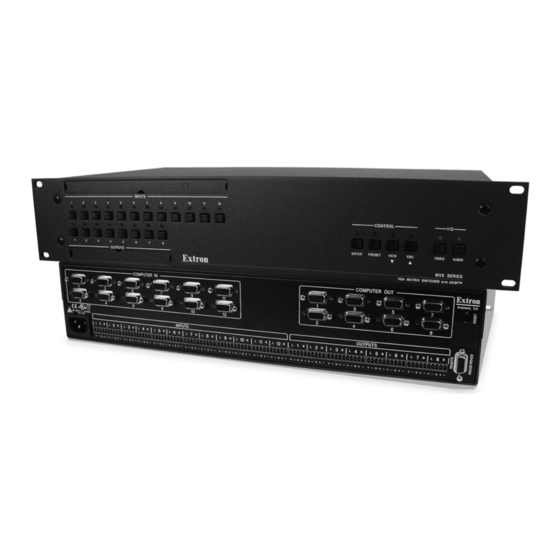
Introduction About this Manual This manual contains installation, confi guration, and operating information for the Extron MVX 128 A 12-input by 8-output wideband computer video (VGA) and audio matrix switcher. About the MVX 128 A Matrix Switcher The MVX matrix switcher distributes any of 12 inputs to any combination of 8 outputs. -
Page 9: Defi Nitions
The switcher has an internal 100 VAC to 240 VAC, 50/60 Hz, 15 watts autoswitchable power supply that provides worldwide power compatibility. The MVX 128 A has a minimum bandwidth of 300 MHz (-3 dB). The switcher can also switch RGBS, RGsB, RsGsBs, HDTV, component video, S-video, and composite video. -
Page 10: Features
Remote control panels and keypads — The matrix switchers are remote controllable, using the optional MKP 2000 and MKP 3000 remote control keypads. The remote control devices are easy to use and provide tactile buttons for quick selection. MVX 128 A VGA Matrix Switchers • Introduction... - Page 11 SIS command is required to unlock the front panel controller before it can be operated. Power — The matrix switcher’s 100 VAC to 240 VAC, autoswitchable, internal power supply provides worldwide power compatibility. MVX 128 A VGA Matrix Switchers • Introduction ™ or comparable labeler.
- Page 12 Introduction, cont’d MVX 128 A VGA Matrix Switchers • Introduction...
-
Page 13: Chapter Two • Installation
MVX 128 A VGA Matrix Switchers Chapter Two Installation Mounting the Switcher Cabling and Rear Panel Views... -
Page 14: Mounting The Switcher
Installation Mounting the Switcher The MVX 128 A is housed in a rack-mountable, 2U high metal enclosure with mounting fl anges for standard 19” racks. If desired, rack mount the switcher as follows: Insert the switcher into the rack, aligning the holes in the mounting bracket with those in the rack. -
Page 15: Audio Connections
Ethernet or RS-232/RS-422 control to ensure that the level on the output does not vary from input to input. See chapter 3, Operation; chapter 4, Programmer’s Guide; and chapter 5, Matrix Software for details. MVX 128 A VGA Matrix Switchers • Installation Ring Ring... -
Page 16: Rs-232/Rs-422 Connection
If desired, connect an MKP 2000 or MKP 3000 remote control panel to the switcher’s RS-232/RS-422 connector. Refer to the MKP 2000 Remote Control Panel User’s Manual and the MKP 3000 User’s Manual for details. MVX 128 A VGA Matrix Switchers • Installation Ring Sleeve (s) -
Page 17: Reset Button
Power connection AC power connector — Plug a standard IEC power cord into this connector to connect the switcher to a 100 VAC to 240 VAC, 50 or 60 Hz power source. MVX 128 A VGA Matrix Switchers • Installation... - Page 18 Installation, cont’d MVX 128 A VGA Matrix Switchers • Installation...
-
Page 19: Chapter Three • Operation
MVX 128 A VGA Matrix Switchers Chapter Three Operation Front Panel Controls and Indicators Front Panel Operations Rear Panel Controls Optimizing the Audio Troubleshooting Confi guration Worksheets... -
Page 20: Front Panel Controls And Indicators
The control buttons and video/audio (I/O) selection buttons are grouped on the right side of the panel. Figure 3-1 — Front panel, MVX 128 A Defi nitions The following terms, which apply to all Extron matrix switchers, are used throughout this manual: Tie —... -
Page 21: Input And Output Buttons
(fi gure 3-2). See chapter 5, Matrix Software, for details on using the label software. Rack DVD (DVS 308) Figure 3-2 — Sample label MVX 128 A VGA Matrix Switchers • Operation ™ labeler. Each input and output can be labeled with INPUTS... -
Page 22: Control Buttons
Indicates that the RS-232/RS-422 port is set to 19200 baud in Serial Port Confi guration mode. See Selecting the RS-232/RS-422 protocol and baud rate on page 3-33. MVX 128 A VGA Matrix Switchers • Operation Specify RGBHV, audio, or both (see I/O selection buttons [ Press the desired input button ( Press the desired output button(s) ( Press the Enter button. - Page 23 Indicates that the RS-232/RS-422 port is set to 115200 baud in Serial Port Confi guration mode. See Selecting the RS-232/RS-422 protocol and baud rate on page 3-33. MVX 128 A VGA Matrix Switchers • Operation < ) button and LED have two primary >...
-
Page 24: I/O Controls
Indicates that the RS-232/RS-422 port is set to the RS-422 protocol in Serial Port Confi guration mode. See Selecting the RS-232/RS-422 protocol and baud rate on page 3-33. MVX 128 A VGA Matrix Switchers • Operation ) and Audio ( ) buttons. -
Page 25: Front Panel Operations
If an error occurs during the self-test, the switcher locks up and does not operate. If your switcher locks up on power-up, call the Extron S Hotline. Sales & Technical Support MVX 128 A VGA Matrix Switchers • Operation... -
Page 26: Creating A Confi Guration
• • MVX 128 A VGA Matrix Switchers • Operation Only one video input and one audio input can be tied to an output. If a tie is made between an input and an output, and the selected output was previously tied to another input, the older tie is broken in favor of the newer tie. -
Page 27: Example 1: Creating A Set Of Video And Audio Ties
Press and release the Input 5 button. The LED lights. Figure 3-5 — Select an input MVX 128 A VGA Matrix Switchers • Operation RGBHV AUDIO Press the Audio button to toggle on and off. The LED lights when selected. - Page 28 Input 5 (video and audio) are tied to output 3, output 4, and output 8 Input 5 (video/audio) tied Figure 3-8 — Example 1, fi nal confi guration MVX 128 A VGA Matrix Switchers • Operation 3-10 OUTPUTS The Enter LED and all input LEDs and output LEDs return to the unlit state.
-
Page 29: Example 2: Adding A Tie To A Set Of Video And Audio Ties
The Output 3, Output 4, and Output 8 LEDs light to indicate the RGBHV ties created in example 1. OUTPUTS OUTPUTS MVX 128 A VGA Matrix Switchers • Operation ENTER PRESE The Enter LED blinks to indicate the need to confirm the change. - Page 30 Input 5 (audio) is tied to output 3, output 4, and output 8 to outputs 1, 3, 4, and 8. Figure 3-14 — Example 2, fi nal confi guration MVX 128 A VGA Matrix Switchers • Operation 3-12 The Enter LED and all input LEDs and output LEDs return to the unlit state.
-
Page 31: Example 3: Removing A Tie From A Set Of Video And Audio Ties
The Output 3, Output 4, and Output 8 LEDs light to indicate the audio ties created in example 1. The Output 1 LED does not light to indicate the tie created in example 2 because that tie is RGBHV only. OUTPUTS MVX 128 A VGA Matrix Switchers • Operation 3-13... - Page 32 Audio — Input 5 (audio) is tied to output 3 and output 8 to outputs 1, 3, 4, and 8. Figure 3-20 — Example 3, fi nal confi guration MVX 128 A VGA Matrix Switchers • Operation 3-14 OUTPUTS The Enter LED and all input LEDs and output LEDs return to the unlit state.
-
Page 33: Viewing A Confi Guration
CONTROL ENTER PRESET VIEW = Blink once The LED blinks once. Figure 3-21 — Clear all selections Press and release the View button to enter View-Only mode. The View LED lights. MVX 128 A VGA Matrix Switchers • Operation 3-15... - Page 34 LED, the tied input LED (input 5), and the output LEDs light for all of the outputs that are tied to the input. MVX 128 A VGA Matrix Switchers • Operation 3-16 In this example, the Audio LED blinks to indicate audio breakaway (assuming you have performed example 1, 2, and 3).
- Page 35 LEDs return to the unlit state. Figure 3-26 — Press the View button to exit View-Only mode MVX 128 A VGA Matrix Switchers • Operation The output buttons for outputs that are tied to input 5 light to indicate audio ties (audio breakaway).
-
Page 36: Muting And Unmuting Video And/Or Audio
Figure 3-27 — Clear all selections Press and release the View button to enter View-Only mode. The View LED lights. MVX 128 A VGA Matrix Switchers • Operation 3-18 You can mute video and audio, video-only, or audio-only outputs. Pressing and releasing the RGBHV button and the Audio button toggles each selection on and off. - Page 37 N If both RGBHV and audio are selected and only video is muted, the output LED fl ashes. If only audio is selected, the output LED is lit steadily (indicating no audio mute). MVX 128 A VGA Matrix Switchers • Operation OUTPUTS OUTPUTS...
- Page 38 Press the View button to exit View-Only mode. CONTROL SET VIEW Figure 3-31 — Press the View button to exit View-Only mode MVX 128 A VGA Matrix Switchers • Operation 3-20 Press and hold the Output 3 and Output 4 button. OUTPUTS...
-
Page 39: Using Global Presets
Press and release the Esc button (fi gure 3-33). Press the Esc button to clear all selections. CONTROL ENTER PRESET VIEW = Blink once The LED blinks once. Figure 3-33 — Clear all selections MVX 128 A VGA Matrix Switchers • Operation Preset Preset Preset Preset Preset Preset... - Page 40 The Enter and Preset LEDs return to the unlit state. Figure 3-36 — Press the Enter button MVX 128 A VGA Matrix Switchers • Operation 3-22 All input and output LEDs with assigned presets light. If you then save the configuration to a lit preset number, the configuration data at that preset location will be overwritten.
-
Page 41: Example 7: Recalling A Preset
Preset 13 Preset 14 Preset 15 Preset 16 = Blinking LED Figure 3-39 — Select the preset MVX 128 A VGA Matrix Switchers • Operation All input and output LEDs with assigned presets light. Unlit (Preset Assigned) (Preset Unassigned) -
Page 42: Viewing And Adjusting The Input Audio Level
Press the Esc button to clear any input LEDs, output LEDs, or control LEDs that are lit. To enter the Audio mode, press and hold the Audio button until the LED begins to blink, then release the button. MVX 128 A VGA Matrix Switchers • Operation 3-24 CONTROL All input LEDs return to the unlit state. - Page 43 Exiting Audio mode by pressing the Audio button always returns the I/O confi guration to RGBHV and audio selected for confi guration. MVX 128 A VGA Matrix Switchers • Operation Audio input level settings Output LED View Esc > = on,...
-
Page 44: Example 10: Viewing And Adjusting An Input Audio Level
In this example, the output buttons and View and Esc buttons display an audio gain level of +8 dB. = Lit LED, = Unlit LED, Figure 3-44 — Select an input and read the audio level MVX 128 A VGA Matrix Switchers • Operation 3-26 CONTROL The LED blinks once. - Page 45 RGBHV AUDIO The Audio LED stops blinking and lights steadily. The RGBHV button lights. Figure 3-46 — Deselect Audio mode MVX 128 A VGA Matrix Switchers • Operation < ) button once (fi gure 3-45) to decrease the input <...
-
Page 46: Viewing And Adjusting The Output Volume
Press and release the Audio button to save the audio settings and exit the Audio mode. The Audio button stops blinking. N • • • • MVX 128 A VGA Matrix Switchers • Operation 3-28 > < ) and View ( ) buttons to increase and decrease There is one audio volume level setting per output. -
Page 47: Reading The Displayed Volume
Push Esc ( ) button 19 times — 10% + (19•1.5%) = 38.5% volume. The Input 1 through 4 LEDs light steadily. MVX 128 A VGA Matrix Switchers • Operation Audio output volume settings Output dB of Input LED volume attenuation 5.5%... -
Page 48: Example 11: Viewing And Adjusting An Output Volume Level
Press and hold the Audio button for approximately 2 seconds (fi gure 3-48). Press and hold the Audio button. RGBHV AUDIO = Blinking LED Figure 3-48 — Select Audio mode MVX 128 A VGA Matrix Switchers • Operation 3-30 CONTROL The LED blinks once. 2 seconds AUDIO The LED blinks to indicate Audio mode. - Page 49 RGBHV AUDIO The Audio LED stops blinking and lights steadily. The RGBHV button lights. Figure 3-51 — Deselect Audio mode MVX 128 A VGA Matrix Switchers • Operation –39 dB attenuation, 41.5% volume INPUTS >...
-
Page 50: Locking Out The Front Panel (Executive Mode)
LEDs return to the unlit state and the RGBHV and Audio LEDs turn on. Release the RGBHV and Audio buttons. Figure 3-53 — System reset MVX 128 A VGA Matrix Switchers • Operation 3-32 The RGBHV and Audio LEDs blink twice to 2 seconds indicate the mode change. -
Page 51: Selecting The Rs-232/Rs-422 Protocol And Baud Rate
ENTER PRESET VIEW = Lit LED, = Blinking LED Figure 3-55 — RS-232/RS-422 and baud rate selection MVX 128 A VGA Matrix Switchers • Operation CONTROL ENTER PRESET VIEW All Control LEDs light with one flashing. Both I/O LEDs light with one flashing. -
Page 52: Rear Panel Operations
Release the Reset button and then immediately press and release the Reset button again. The reset does not occur if the second momentary press does not occur within 1 second. MVX 128 A VGA Matrix Switchers • Operation 3-34 CONTROL ENTER PRESET VIEW All Control LEDs return to the unlit state. -
Page 53: Performing A Hard Reset From The Rear Panel
As necessary, adjust the output audio level of each input (see Viewing and adjusting the output volume, on page 3-28). Power RESET Release the Reset button. MVX 128 A VGA Matrix Switchers • Operation 3-35... -
Page 54: Troubleshooting
Use different colors for video and audio. Worksheet example 1: System equipment Figure 3-59 shows a worksheet for an MVX 128 A in a fi ctional organization with the system hardware annotated. Inputs 10 and 11 have no connection in this organization, so they have been crossed out on the worksheet. -
Page 55: Worksheet Example 2: Daily Confi Guration
Classical music from the CD player (input 5) is: Played in the background in the main hall on sound system #2 (output 5) Played in the lobby (output 8) MVX 128 A VGA Matrix Switchers • Operation Input sources Classroom... -
Page 56: Worksheet Example 3: Test Confi Guration
Fill in the preset number and use colors, or dashes, etc. to make connecting lines. Indicate if the configuration is for Video, Audio, or both. Figure 3-61 — Worksheet example 3: Test confi guration MVX 128 A VGA Matrix Switchers • Operation 3-38 Input sources... - Page 57 MVX 128 A VGA Matrix Switchers • Operation 3-39...
- Page 58 Operation, cont’d MVX 128 A VGA Matrix Switchers • Operation 3-40...
-
Page 59: Chapter Four • Programmer's Guide
MVX 128 A VGA Matrix Switchers Chapter Four Programmer’s Guide Host-to-Switcher Instructions Switcher-Initiated Messages Switcher Error Responses Using the Command/Response Tables Command/Response Table for SIS Commands Special Characters... -
Page 60: Host-To-Switcher Instructions
• 9600 baud • 1 stop bit N The MVX 128 A switcher can support either RS-232 or RS-422 serial communication protocol, and can operate at 9600, 19200, 38400, or 115200 baud rates. See Selecting the RS-232/RS-422 protocol and baud rate on page 3-33, Operation, to confi... -
Page 61: Switcher Error Responses
ASCII to HEX Conversion Table Space Symbols are used throughout the table to represent variables in the command/ response fi elds. Command and response examples are shown throughout the table. MVX 128 A VGA Matrix Switchers • Programmer’s Guide... -
Page 62: Command/Response Table For Sis Commands
= Stop bits = Port type = Voltage = Temperature MVX 128 A VGA Matrix Switchers • Programmer’s Guide 01 – 12 00 – 12 (00 = untied) 01 – 08 –18 to +24 (45 steps of gain or attenuation) 0 –... -
Page 63: Command/Response Table For Sis Commands
N The & read tie command for RGB and the % read tie command for video can be used interchangeably on the matrix switchers. Read RGB output tie & Read video output tie Read audio output tie MVX 128 A VGA Matrix Switchers • Programmer’s Guide Response (switcher to host) • • •... - Page 64 Read output volume Audio mute commands Audio mute Audio unmute Read audio mute Global audio mute Global audio unmute MVX 128 A VGA Matrix Switchers • Programmer’s Guide Response Additional description (switcher to host) Mute output (video off). Unmute output (video on).
- Page 65 Output value attenuation volume 5.5% 8.5% 11.5% 14.5% 17.5% 20.5% 23.5% 26.5% 29.5% 32.5% 35.5% MVX 128 A VGA Matrix Switchers • Programmer’s Guide dB of Output value value attenuation volume 38.5% 41.5% 44.5% 47.5% 50.5% 53.5% 56.5% 59.5% 62.5% 65.5%...
- Page 66 Directly write a global preset Example: +27P0*! +27P12*5!10*09%3*2$3*8& Executive mode Lock front panel Unlock front panel View lock status MVX 128 A VGA Matrix Switchers • Programmer’s Guide Response (switcher to host) X( , X2@] Nmg01 Security 1 X1#] Security 2 displays [unassigned].
- Page 67 View audio output tie Example: View input gain Example: View output volume Example: View output mutes Example: MVX 128 A VGA Matrix Switchers • Programmer’s Guide Response (switcher to host) X&] , ... 02301000Mut Additional description Clear all global presets and their names.
- Page 68 Each position shown in the response is an output: left = output 1, right = output 16. (Outputs 9 through 16 are not present on the MVX 128 A.) The number in each position is the input tied to that output.
- Page 69 MVX 128 firmware version for this switcher model Request system status • Response description: +3.3V Example: 3.3V power system at 3.29V MVX 128 A VGA Matrix Switchers • Programmer’s Guide Response (switcher to host) • V12X08 A12X08 60-799-01 X1!] 1.23...
- Page 70 Programmer’s Guide, cont’d MVX 128 A VGA Matrix Switchers • Programmer’s Guide 4-12...
-
Page 71: Chapter Five • Matrix Software
MVX 128 A VGA Matrix Switchers Chapter Five Matrix Software Matrix Switchers Control Program Button Label Generator Program... -
Page 72: Matrix Switchers Control Program
N The program was designed to control most Extron matrix switchers, but its operation is limited to the features and confi guration of your switcher. N The MVX 128 A switcher can support either RS-232 or RS-422 serial communication protocol, and operate at 9600, 19200, 38400, or 115200 baud rates. -
Page 73: Using The Software
The Comm Port Selection window (fi gure 5-1) appears. Figure 5-1 — Comm port selection window Choose either the comm port that is connected to the MVX 128 A switcher’s RS-232/RS-422 port or Emulate. N Although IP [LAN] is available for selection, the switcher does not have an Ethernet port. - Page 74 fi gure 5-3) appears. The window displays the current confi guration of the attached matrix. Figure 5-2 — Extron Matrix Switcher Control Program window (blank) Figure 5-3 — Sample program window (complete) MVX 128 A VGA Matrix Switchers • Matrix Software...
-
Page 75: Updating Fi Rmware
Run the executable (*.exe) fi le to decompress the fi rmware fi le. Start the Matrix Switcher Control Program and connect to the MVX 128 A switcher. See Using the software in this chapter, steps 1 through 4, starting on page 5-3. - Page 76 fi rmware upgrade. N The original factory-installed fi rmware is permanently available on the MVX 128 A switcher. If the attempted fi rmware upload fails for any reason, the switcher reverts to the factory-installed fi rmware. Click the Open button. A status window, which shows the progress of the upload, appears (fi...
-
Page 77: Windows Buttons, Drop Boxes, And Trashcan
Select printer — Selects the target printer. Print tie map — Prints the tie set that is displayed on the screen. Exit — Closes the Matrix Switcher Control Program. MVX 128 A VGA Matrix Switchers • Matrix Software... -
Page 78: Tools Menu
Hardware status — Provides an overall view of the status of the matrix switcher, including the power supply voltages, the temperature status, the Remote RS-232/RS-422 port confi guration, and the installed and updated fi rmware status (fi gure 5-6). Figure 5-6 — Status window MVX 128 A VGA Matrix Switchers • Matrix Software... -
Page 79: Preferences Menu
Take button are indicated by +. Ties that will be broken when you click on the Take button are indicated by –. Figure 5-8 — Ties shown as crosspoints MVX 128 A VGA Matrix Switchers • Matrix Software... -
Page 80: Master-Reset Selection
The program is contained on the same CD-ROM as the Matrix Switcher Control Program and is also available on the Extron Web site, www.extron.com. MVX 128 A VGA Matrix Switchers • Matrix Software 5-10... -
Page 81: Appendix A • Specifi Cations, Part Numbers, Accessories
MVX 128 A VGA Matrix Switchers A ppendix A Specifi cations, Part Numbers, Accessories Specifi cations Part Numbers and Accessories Button Labels... -
Page 82: Video Input
Output impedance ... 75 ohms Max input voltage ... 5.0 Vp-p Max. propagation delay ... 30 ns Max. rise/fall time ... 4 ns Polarity... Positive or negative (follows input) MVX 128 A VGA Matrix Switchers • Specifi cations, Part Numbers, Accessories ™... -
Page 83: Audio Input
RS-422: 2 = TX-, 3 = RX-, 5 = GND, 7 = RX+, 8 = Tx+ Program control ... Extron’s control/confi guration program for Windows Extron’s Simple Instruction Set (SIS MVX 128 A VGA Matrix Switchers • Specifi cations, Part Numbers, Accessories ® ™... - Page 84 Compliances ... CE, FCC Class A, VCCI, AS/NZS, ICES MTBF ... 30,000 hours Warranty ... 3 years parts and labor All nominal levels are at ±10%. Specifi cations are subject to change without notice. MVX 128 A VGA Matrix Switchers • Specifi cations, Part Numbers, Accessories...
-
Page 85: Included Parts
Part Numbers and Accessories Included parts These items are included in each order for a MVX 128 A matrix switcher: Included parts MVX 128 A Tweeker (small screwdriver) MVX 128 A user’s manual Captive screw audio connectors (20) Matrix Switchers Control Program and... -
Page 86: Cables
VGA M35’ MHR, 35’ (10.6 m) VGA M50’ MHR, 50’ (15.2 m) VGA M75’ MHR, 75’ (22.8 m) VGA M100’ MHR, 100’ (30.4 m) MVX 128 A VGA Matrix Switchers • Specifi cations, Part Numbers, Accessories Part number 26-112-17 26-112-15... -
Page 87: Button Labels
MVX 128 A VGA Matrix Switchers • Specifi cations, Part Numbers, Accessories... - Page 88 Specifi cations, Part Numbers, Accessories, cont’d MVX 128 A VGA Matrix Switchers • Specifi cations, Part Numbers, Accessories...
-
Page 89: Fcc Class A Notice
Note: This equipment has been tested and found to comply with the limits for a Class A digital device, pursuant to part 15 of the FCC Rules. These limits are designed to provide reasonable protection against harmful interference when the equipment is operated in a commercial environment. - Page 90 Extron Electronics, USA 1230 South Lewis Street Anaheim, CA 92805 714.491.1500 www.extron.com Fax 714.491.1517 Extron Electronics, Europe Extron Electronics, Asia Beeldschermweg 6C 135 Joo Seng Road, #04-01 3821 AH Amersfoort PM Industrial Building The Netherlands Singapore 368363 +31.33.453.4040 +65.6383.4400 Fax +31.33.453.4050 Fax +65.6383.4664 ©...
Need help?
Do you have a question about the MVX 128 and is the answer not in the manual?
Questions and answers