Extron electronics MPX 423 A User Manual
Media presentation matrix switcher
Hide thumbs
Also See for MPX 423 A:
- Quick manual (4 pages) ,
- User manual (56 pages) ,
- User manual (48 pages)
Table of Contents
Advertisement
Quick Links
Download this manual
See also:
Quick Manual
Advertisement
Table of Contents

Related Manuals for Extron electronics MPX 423 A


Summary of Contents for Extron electronics MPX 423 A
- Page 1 MPX 423 A Media Presentation Matrix Switcher 68-972-01 Rev. B 12 07...
- Page 2 Precautions Safety Instructions • English This symbol is intended to alert the user of important operating and maintenance (servicing) instructions in the literature provided with the equipment. This symbol is intended to alert the user of the presence of uninsulated dangerous voltage within the product’s enclosure that may present a risk of electric shock.
- Page 3 FCC Class A Notice This equipment has been tested and found to comply with the limits for a Class A digital device, pursuant to part 15 of the FCC Rules. Operation is subject to the following two conditions: (1) this device may not cause harmful interference, and (2) this device must accept any interference received, including interference that may cause undesired operation.
- Page 5 For audio output, connect up to two audio output devices. Refer to Chapter 2, Installation, for wiring diagrams. Step 7 If the MPX 423 A matrix switcher is to be connected to a computer or host controller for remote control, Connect the host controller’s RS-232 cable to the 9-pin, female RS-232 remote connector of the switcher (see pinout table on the following page).
- Page 6 Quick Start — MPX 423 A, cont’d RS-232 — — — — — — RS-232 remote connector pinout table And/or Plug one end of a CAT 5, straight-through Ethernet cable to the RJ-45 LAN port of the switcher. See below for pinout instructions.
-
Page 7: Table Of Contents
Table of Contents Chapter One • Introduction About This Manual ... 1-2 About the MPX 423 A Media Presentation Matrix Switcher Features ..1-2 Chapter Two • Installation Mounting the Matrix Switcher Tabletop.use ..2-2 Rack.mounting.the.switcher. - Page 8 ... A-5 Cables ..A-5 Assorted.connectors ... A-6 Pre-cut.cables ..A-6 All trademarks mentioned in this manual are the properties of their respective owners. MPX 423 A • Table of Contents ... 4-1 ... 4-2 ..4-2 ... 4-2 ... 4-3 ... 4-3 ... 4-3 ..4-4 ...
-
Page 9: Chapter One • Introduction
MPX 423 A Matrix Switcher Chapter One Introduction About.This.Manual About.the.MPX.423.A.Media.Presentation.Switcher Features... -
Page 10: About The Mpx 423 A Media Presentation Matrix Switcher
Media Presentation Matrix Switcher. About the MPX 423 A Media Presentation Matrix Switcher The MPX 423 A is a matrix switcher that supports both single and separate switching modes and merges the following independent switchers into a single, compact enclosure: •... - Page 11 Speed-sensitive volume control — Automatic sensitivity control allows the user to easily fine-tune the audio volume. Versatile mounting options — The MPX 423 A is housed in a rugged, 1U, full rack width metal enclosure, and can be easily mounted into any rack or podium, or under a desk.
- Page 12 Introduction, cont’d MPX 423 A • Introduction...
-
Page 13: Chapter Two • Installation
MPX 423 A Matrix Switcher Chapter Two Installation ...Mounting.the.Matrix.Switcher Rear.Panel.Connectors Connecting.the.Matrix.Switcher RS-232.and.Ethernet.Control... -
Page 14: Tabletop.use
Installation Mounting the Matrix Switcher MPX 423 A Matrix Switchers are housed in 1U high, 17.4” wide metal enclosures that are rack- or desk-mountable. A rack/desk mounting kit (#70-077-03) is supplied with each switcher. A switcher may also be mounted under a table, desk, or podium, or on a wall, using the optional under-desk mounting kit (#70-222-01). -
Page 15: Rack.mounting.instructions
Figure 2-1 — Mounting the switcher Furniture mounting the switcher The MPX 423 A can be mounted under a table or other horizontal surface with an optional Extron under-desk mounting kit (part #70-222-01). Secure the two table/wall mounting brackets included in the under-desk mounting kit to the switcher with the eight machine screws provided in the kit (figure 2-1). -
Page 16: Rear Panel Connectors
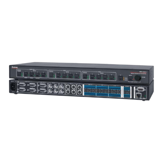
100-240V 0.3A 50/60 Hz Figure 2-2 — Rear panel of MPX 423 A AC power — Standard AC power connector for a power source of 100 – 240 VAC, operating at 50/60 Hz. VGA input group — Four female 15-pin HD connectors for RGB video input (numbered 1 to 4). -
Page 17: Connecting The Matrix Switcher
Turn off power to the MPX 423 A matrix switcher and all other devices that will be connected. Mount the MPX 423 A in the desired position on a desk, in a rack, or under a table as described previously in this chapter. -
Page 18: Rs-232 And Ethernet Control
The protocol is 9600 baud, 8-bit, 1 stop bit, no parity, and no flow control. The MPX 423 A is also compatible with baud rates 19200, 38400, and 115200. For Ethernet control, connect a CAT 5, straight-through Ethernet cable to the RJ-45 LAN port of the switcher. -
Page 19: Chapter Three • Operation
MPX 423 A Matrix Switcher Chapter Three Operation Front.Panel.Operation Switcher.Modes.and.Operation Audio. Resetting.the.Unit... - Page 20 • Functions with the Mute button to set an RGB delay. Mode — This is the secondary function of this button (see function of this button allows the MPX 423 A to be used in either “single” or “separate” mode.
-
Page 21: Introduction.to.single.switcher.mode
MODE SINGLE SEPARATE Figure 3-2 — MPX 423 A matrix switcher front panel Introduction to single switcher mode In single switcher mode, the switcher emulates a 1 output switcher with 12 inputs. When a video input signal is tied to an output, it is routed to the output of the same video signal format. -
Page 22: Establishing.a.tie
Select the input from any of the 12 inputs. Reading the LEDs Reading the LEDs of the MPX 423 A matrix switcher is the primary means of controlling your inputs and outputs. The unit uses a series of LED colors and actions to indicate the status of each group and/or tie. -
Page 23: Muting.and.unmuting.video.and/Or.audio
Press and hold the S-video output button for 2 seconds to mute the selected S-video output. N Since the video groups share the audio outputs, audio outputs can be muted in any video group. To avoid unwanted audio mute, select video only or audio only by pressing the I/O button before muting the selected output. N Mutes are saved to nonvolatile memory. When power is removed and restored, the mute settings are retained. N To view the mute status, it is recommended to select video only or audio only (I/O button) and toggle output buttons on any video group. The muted output LED will blink. N Selecting video & audio (I/O button) to view muted outputs is not recommended. Blinking output LEDs could also mean an audio or follow-all tie. INPUTS SINGLE SEPARATE Separate button MPX 423 A • Operation... -
Page 24: Locking.and.unlocking.the.front.panel
Video group inputs. The source at input 9 provides the Genlock sync signal to all of the S-Video group inputs. This happens automatically when inputs are connected to inputs 5 and 9. No configuration is required. MPX 423 A • Operation MPX 423 A VOLUME... -
Page 25: Audio
Audio The MPX 423 A is also a 12x2 audio matrix switcher, where any of the 12 inputs can be routed to one or both outputs simultaneously. Establishing an audio tie Regardless of the video switching mode to which the unit is configured (single or separate), the MPX 423 A also emulates a 12x2 audio switcher. -
Page 26: Adjusting.the.input.audio.level
Press and release the I/O button or wait 30 seconds for the unit to exit the audio adjustment mode. Audio outputs Balanced or unbalanced audio output is available on the MPX 423 A using a 3.5 mm, 5-pole captive screw connector, wired as shown below. See caution... -
Page 27: Resetting The Unit
Mode 5 reset. Factory reset modes Factory resets can be set using the front panel I/O button. To reset the MPX 423 A to factory defaults Press and hold the I/O button on the front panel while plugging in AC power. - Page 28 Operation, cont’d 3-10 MPX 423 A • Operation...
-
Page 29: Chapter Four • Sis Programming And Control
MPX 423 A Matrix Switcher Chapter Four SIS Programming and Control Remote.Control.Port.(RS-232) Host-to-MPX.423.A.Communications Commands.and.Responses... -
Page 30: Mpx.423.A-Initiated.messages
A string is one or more characters. MPX 423 A-initiated messages If you are communicating with the MPX 423 A via RS-232 or via a verbose Telnet connection, when a local event such as a front panel selection or adjustment takes place, the unit responds by sending a message to the host. -
Page 31: Password.information
Error responses If the MPX 423 A is unable to execute a command, it returns an error response to the host. The error response codes and their descriptions are as follows: E01 –... -
Page 32: Commands And Responses
Commands and Responses Using the command/response tables The MPX 423 A can be controlled via a Telnet connection (port 23) or a Web browser connection (port 80). The ASCII and URL commands listed in the tables starting on page 4-9 perform the same functions, but are encoded differently to accommodate the requirements of each port (Telnet or Web browser). -
Page 33: Symbol.definitions
= Flow control: Hardware, Software, None = Data pacing (specified in milliseconds between bytes): 0000 - 1000 (default = 0 ms) =Web page priority flag (internal use only): 0 = internal (default on power-up) 1 = user MPX 423 A • SIS Programming and Control... -
Page 34: Command/Response Table For Sis Commands
Example Response: 06 12 -- -- -- -- -- -- -- -- -- -- -- -- -- -- Aud Audio output 1 is tied to input 06. / Audio output 2 is tied to input 12. Read video output tie Read RGBHV output & MPX 423 A • SIS Programming and Control Response (switcher to host) X#• X@•... - Page 35 •Vol X&] •Vol X&] Amt1 Amt0 X1#] •Dly X1#] MPX 423 A • SIS Programming and Control Additional description Audio input tied to audio output Read output volume for audio output 1 or 2. Set output to switcher mode Read the mode of switcher...
- Page 36 Unlock all front panel 0X/x functions View lock status Request Information Request Part Number Example: MPX 423 A • SIS Programming and Control Response Additional description (switcher to host) Mute output 1 = mute on, 0 = mute off Unmute output on).
- Page 37 + ~ @ = ‘ [ ] { } < > : | \ ? X3&] X3& = GMT date: (MM/DDD/YY•HH:MM:SS) X2^] = GMT date: [WWW,•DD•MMM•YYYY• HH:MM:SS•GMT] X3(] = GMT offset (-12.0 through 14.0 hours and minutes removed from GMT) MPX 423 A • SIS Programming and Control...
- Page 38 View receive timeout EX4% Set DHCP on or off Read DHCP status EX2& Set IP address Read IP address Read hardware (MAC) 4-10 MPX 423 A • SIS Programming and Control Response (switcher to host) X3(] X4)] X4)] X4& Cpnx1•Ccp, X5)] X4&...
- Page 39 X2&] X2&] X2&] X3)] Ipa• X3)] X3)] Ipu• X3)] X5$] X5$] X3!] MPX 423 A • SIS Programming and Control Additional description X2& = IP address (###.###.###.###) X2& = IP address (###.###.###.###) X2& = IP address (###.###.###.###) X2& = IP address (###.###.###.###)
- Page 40 Programming and Control, cont’d ™ 4-12 MPX 423 A • SIS Programming and Control...
-
Page 41: Chapter Five • Ethernet Control
MPX 423 A Matrix Switcher Chapter Five Ethernet Control Accessing.and.Using.the.Web.Server Navigating.the.Default.Web.Pages Special.Characters... - Page 42 Ethernet Control The MPX 423 A matrix switcher features an on-board Web server, displayed as a set of default Web pages. These pages allow you to control and operate the MPX unit through its Ethernet port, connected via a LAN or WAN, using a Web browser such as the Microsoft Internet Explorer (version 5.5 or higher), or Netscape Navigator...
-
Page 43: Navigating The Default Web Pages
(figure 5-2), also known as the System Status page. Navigating the Default Web Pages The MPX 423 A default Web pages include four tabs (Status, Configuration, File Management, and Control) for easy navigation of the administrative options including system status, password control, file management, and video/audio settings. -
Page 44: Dsvp.page
The DSVP page, accessible from the Status tab, allows you to view a snapshot-in- time of the input frequencies of connected inputs on the Digital Sync Validation Processing (DSVP) page (see figure 5-3). Figure 5-3 — DSVP page MPX 423 A • Ethernet Control... -
Page 45: Configuration.tab
Configuration tab The Configuration tab includes pages that show the current System Settings, Passwords, and Firmware Upgrade data for the MPX 423 A. System Settings page The Systems Settings page (figure 5-4) consists of fields where you can view and edit IP administration and system settings. - Page 46 Gateway IP Address The Gateway IP Address field identifies the address of the gateway to the mail server to be used if the MPX 423 A switcher and the mail server are not on the same subnet. The gateway IP address has the same parameters rules as the system IP address.
-
Page 47: Passwords.page
As shown in figure 5-5, password-protected connections allow two levels of protection: administrator and user. Administrators have full access to all MPX 423 A switching capabilities and editing functions. Users can only create ties, set video and audio mutes, and view all settings, with the exception of passwords. -
Page 48: Firmware.upgrade.page
Figure 5-6 — Firmware Upgrade page N The Firmware Upgrade page is only for replacing the firmware that controls all switcher operation. To insert your own HTML pages, see “File Management” later in this chapter. Insure that your PC is connected to the MPX 423 A switcher via the switcher’s Ethernet port. Update the switcher firmware as follows: Visit the Extron web site at www.extron.com. Click the Download tab. - Page 49 Scroll to the MPX 423 A firmware file. Click the Download link in the far right column. Figure 5-8 — MPX 423 A firmware file and Download link Complete the Personal Information form. Click the Download MPX423A_FW1x02.exe button. Figure 5-9 — Personal Information form...
- Page 50 N Valid firmware files must have the file extension ‘.S19’. Any other file extension is not a firmware upgrade. N The original factory-installed firmware is permanently available on the MPX 423 A switcher. If the attempted firmware upload fails for any reason, the switcher automatically reverts to the factory-installed firmware. Click the Open button. Click the Upload button. The firmware upload to the MPX 423 A switcher begins, and may take several minutes to complete. 5-10 MPX 423 A • Ethernet Control...
-
Page 51: File.management.page
Delete button of the next file. If you wish to delete all files, click the Delete All button. The file count will revert to 0 and all pages will be deleted. MPX 423 A • Ethernet Control 5-11... -
Page 52: Control.tab
Use the Set and View Ties page (figure 5-12) to quickly view and change input-to-output ties. The Set and View Ties page shows a representation of the MPX 423 A front panel, where the computer (VGA) inputs, the video (composite) inputs, and the S-video inputs are shown in their 4x2 groupings. -
Page 53: Video.&.Audio.settings.page
Figure 5-14 — Input selection drop-down box Click and drag the slider or click the scroll up ( ) button or scroll down ( ) button until the desired input is visible. Click the desired input. MPX 423 A • Ethernet Control 5-13... -
Page 54: Mute.and.unmute.one.or.all.outputs
Computer group only. With a range of half second increments, the maximum delay possible is 5 seconds. To use the RGB Delay feature Click on the RGB Delay drop box. A drop-down scroll box appears. 5-14 MPX 423 A • Ethernet Control... -
Page 55: Change.the.output.volume.level
Select the desired output (1 or 2). Figure 5-19— Output selection drop-down box Click on the Volume Steps (64 max) drop box (figure 5-20). Select the desired output level (00 to 64) Figure 5-20— Volume steps drop-down box MPX 423 A • Ethernet Control 5-15... -
Page 56: Special Characters
The switcher rejects the following characters: {space} ~ @ = ‘ [ ] { } < > ’ “ semicolon (;) colon (:) | \ and ?. 5-16 MPX 423 A • Ethernet Control Output dB of value... - Page 57 MPX 423 A Matrix Switcher A ppendix A Specifications, Part Numbers, Accessories Specifications Part.Numbers.and.Accessories...
-
Page 58: Appendix A • Specifications, Part Numbers, Accessories
S-video outputs ... 2 S-video Composite video outputs 2 composite video Connectors RGB/VGA outputs ... 2 female 15-pin HD S-video outputs ... 2 female 4-pin mini DIN Composite video outputs 2 female BNC MPX 423 A • Specifications, Part Numbers, Accessories... - Page 59 CMRR ... >75 dB @ 20 Hz to 20 kHz Volume range ... -98 dB to 0 dB (volume numbers 0 to 64 in 1.0 dB steps); Output 2 default = 64 (0 dB) Full attenuation is volume level 0, -98 dB. The default for output 1 is -15 dB, volume level 50. MPX 423 A • Specifications, Part Numbers, Accessories...
-
Page 60: Audio Output
Listings ... UL, CUL Compliances ... CE, FCC Class A, VCCI, AS/NZS, ICES MTBF ... 30,000 hours Warranty ... 3 years parts and labor All nominal levels are at ±10% Specifications are subject to change without notice. MPX 423 A • Specifications, Part Numbers, Accessories ™ ) Microsoft Navigator , Telnet ®... -
Page 61: Part Numbers And Accessories
Part Numbers and Accessories Included parts These items are included in each order for a MPX 423 A Matrix Switcher: Included parts MPX 423 A Rack/desk mounting brackets Tweeker (small screwdriver) IEC power cord MPX 423 IP User’s Manual 4 rubber feet (self-adhesive) 3.5 mm captive screw audio connectors... -
Page 62: Assorted.connectors
BNC-5-75 MHR, 75’ BNC-5-100 MHR, 100’ BNC-5-15 MHR, 150’ BNC-5-200 MHR, 200’ BNC-5-250 MHR, 250’ BNC-5-300 MHR, 300’ N Rolls of bulk cable in lengths up to 5000’ (1524 meters) are available with or without connectors. MPX 423 A • Specifications, Part Numbers, Accessories Part number 22-020-03 22-103-02 22-103-03 Part number 100-074-51 100-075-51 100-076-51... - Page 63 Extron Electronics warrants this product against defects in materials and workmanship for a period of three years from the date of purchase. In the event of malfunction during the warranty period attributable directly to faulty workmanship and/or materials, Extron Electronics will, at its option, repair or replace said products or components, to whatever extent it shall deem necessary to restore said product to proper operating condition, provided that it is returned within the warranty period, with proof of purchase and description of malfunction to:...
- Page 64 Extron Electronics, USA 1230 South Lewis Street Anaheim, CA 92805 800.633.9876 714.491.1500 FAX 714.491.1517 www.extron.com Extron Electronics, Asia Extron Electronics, Europe 135 Joo Seng Rd. #04-01 Beeldschermweg 6C PM Industrial Bldg., Singapore 368363 3821 AH Amersfoort, The Netherlands +800.7339.8766 +65.6383.4400 +800.3987.6673 +31.33.453.4040 FAX +65.6383.4664 FAX +31.33.453.4050...
Need help?
Do you have a question about the MPX 423 A and is the answer not in the manual?
Questions and answers