
Subscribe to Our Youtube Channel
Related Manuals for Extron electronics RAC 104


Summary of Contents for Extron electronics RAC 104
- Page 1 User’s Manual RAC 104 Remote Volume and Tone Controller 68-782-01 Rev. C 12 08...
- Page 2 Precautions Safety Instructions • English This symbol is intended to alert the user of important operating and maintenance (servicing) instructions in the literature provided with the equipment. This symbol is intended to alert the user of the presence of uninsulated dangerous voltage within the product's enclosure that may present a risk of electric shock.
-
Page 3: Fcc Class A Notice
N This unit was tested with shielded cables on the peripheral devices. Shielded cables must be used with the unit to ensure compliance. RAC 104 • Introduction... - Page 4 Table of Contents, cont’d RAC 104 • Table of Contents...
- Page 5 Quick Start Guide — RAC 104 To install and set up the RAC 104 remote volume and tone controller, follow these steps and see the appropriate section of this manual for details: Step 1 Turn all of the equipment off and disconnect the power cords.
- Page 6 Quick Start Guide — RAC 104, cont’d Step 4 If the RAC 104 is to be connected to a computer or host controller for remote control, connect the host’s RS-232 cable to the RAC 104’s 3-pole captive screw RS-232 connector. Wire the connector as shown below.
-
Page 7: Table Of Contents
Front Panel Controls Channel ties ... 2-10 Creating a tie ... 2-10 Cancelling a tie ... 2-11 Resetting the RAC 104 ... 2-11 Locking the front panel ... 2-11 Chapter 3 • Remote Control Simple Instruction Set Host-to-controller instructions ... 3-2 Controller-initiated messages ... - Page 8 Accessories ... A-1 Specifications ... A-2 Included Parts ... A-4 Accessories ... A-4 All trademarks mentioned in this manual are the properties of their respective owners. TOC-ii RAC 104 • Table of Contents Part Numbers, 68-782-01 Rev. C 12 08...
-
Page 9: Chapter 1 • Introduction
RAC 104 Chapter One Introduction About the RAC 104 Features... -
Page 10: About The Rac 104
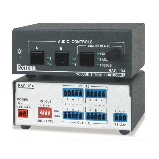
RAC 104’s front panel controls or through a device connected to the unit’s RS-232 connector. The four channels on the RAC 104 can be used as four discrete mono channels or can be tied into pairs as stereo channels. All channels input and output balanced or unbalanced signals on 5-pole captive screw connectors. - Page 11 (-10 dBV) or professional (+4 dBu). Rack, furniture, and projector mountability — The RAC 104 can be mounted on an optional VersaTools or Universal rack shelf. Alternatively, it can be mounted under a desk, podium, or other furniture, or secured to a projector mount with optional brackets.
- Page 12 Introduction, cont’d RAC 104 • Introduction...
-
Page 13: Chapter 2 • Installation And Operation
RAC 104 Chapter Two Installation and Operation Mounting the RAC 104 Rear Panel Features and Cabling Front Panel Controls... -
Page 14: Mounting The Rac 104
Installation and Operation Mounting the RAC 104 The RAC 104 can be set on a table or mounted on a rack shelf, under a desk or tabletop, or on a projector mount. UL rack mounting guidelines The following Underwriters Laboratories (UL) guidelines pertain to the safe installation of the RAC 104 in a rack. -
Page 15: Tabletop Use
Tabletop use Four self-adhesive rubber feet are included with the RAC 104. For tabletop use, attach one foot at each corner of the bottom side of the unit and place the unit in the desired location. Rack mounting For optional rack mounting, do not install the rubber feet. -
Page 16: Furniture Mounting
1/4" of the screw protrudes. Align the mounting screws with the slots in the brackets and place the RAC 104 against the surface, with the screws through the bracket slots. See the illustration below. Slide the RAC 104 slightly forward or back, then tighten all four screws to secure the unit in place. -
Page 17: Projector Mounting
Projector mounting Projector mount the RAC 104 using the optional PMK 100 pole mount kit (part #70-217-01) as follows: Remove rubber feet if they were previously installed on the bottom of the RAC 104. Attach the projector mounting brackets to the RAC 104 with the machine screws provided. -
Page 18: Rear Panel Features And Cabling
Sleeve (s) No Ground here Unbalanced Output Connect the sleeve to ground ( CAUTION sleeve to a negative (-) terminal will damage the audio output circuits. RAC 104 • Installation and Operation INPUTS Tx Rx RS-232 OUTPUTS Ring Sleeve (s) - Page 19 Applying power with incorrect voltage polarity could damage the power supply and the RAC 104. Identify the power cord negative (ground) lead by the ridges on the side of the cord or a black heat shrink wrapping around it.
- Page 20 Installation and Operation, cont’d Your RAC 104 may have shipped with a blue captive screw connector. This blue connector can be plugged into either a blue or an orange power receptacle. The ideal length of exposed (stripped) copper wire for the blue connector is 3/16" (5 mm).
-
Page 21: Front Panel Controls
Front Panel Controls Power LED — Lights to indicate that the RAC 104 is on. Channel selector buttons and LEDs — The RAC 104 has two channel selector buttons, one for channel group A (channels 1 and 2) and one for channel group B (channels 3 and 4). Press and release these buttons to select the channel(s) to adjust. -
Page 22: Channel Ties
The RAC 104 automatically sets both channels to the same volume or tone level using the following criteria: For volume — The unit changes the volume setting for the channel with the highest volume to match that of the other channel. -
Page 23: Cancelling A Tie
(see chapter 3 for more information). Resetting the RAC 104 To return the RAC 104 to its default settings, press and hold the adjustment selector button for 10 seconds. All the LEDs will light and then turn off. The default settings are:... - Page 24 Installation and Operation, cont’d 2-12 RAC 104 • Installation and Operation...
-
Page 25: Chapter 3 • Remote Control
RAC 104 Chapter Three Remote Control Simple Instruction Set Windows-Based Program Control Front Panel Security Lock Out (Executive Modes) Presets Mute... -
Page 26: Simple Instruction Set
Extron Simple Instruction Set (SIS) or the Extron Windows-based control program. The RS-232 connector on the RAC 104 is a 3-pole captive screw connector, with one pole for transmitting data, one for receiving data, and one for the ground. Wire the RS-232 connector as shown below. -
Page 27: Controller Error Responses
Controller error responses When the RAC 104 receives an SIS command and determines that it is valid, it performs the command and sends a response to the host device. If the controller is unable to perform the command because the command is invalid or contains invalid parameters, the contoller returns an error response to the host. - Page 28 DIP switches. DIP switch settings are shown in the table below. Switch Group Input A Input B Output A Off Output B Off Off = -10 dBV (unbalanced, consumer level) On = +4 dBu (balanced, pro level) RAC 104 • Remote Control...
- Page 29 RAC 104 • Remote Control...
- Page 30 Remote Control, cont’d RAC 104 • Remote Control...
- Page 31 RAC 104 • Remote Control...
- Page 32 Remote Control, cont’d RAC 104 • Remote Control...
- Page 33 RAC 104 • Remote Control...
-
Page 34: Windows-Based Program Control
The window also contains channel tie, channel mute, front panel lock out (executive modes), and preset controls. Windows-based control program main window 3-10 RAC 104 • Remote Control... -
Page 35: Input/Output Level Fields
To lock the limits to the values you selected in step 2, click Advanced Setup on the File menu, then click Set Limits. The check mark next to Set Limits disappears. RAC 104 • Remote Control 3-11... -
Page 36: Using The Help System
Locate and select the update file you downloaded from the Web site and click Open. The Firmware Loader loads the update. The RAC 104’s front panel LEDs flash intermittently during the loading process. Once loading is complete, all the LEDs flash simultaneously for 10 seconds and then return to their default settings. -
Page 37: Front Panel Security Lockout (Executive Modes)
When two channels are tied together, selecting mute or unmute for one channel will mute or unmute both. • When the user ties a muted channel to a channel that is not muted, the RAC 104 unmutes the muted channel automatically. RAC 104 • Remote Control 3-13... - Page 38 Remote Control, cont’d 3-14 RAC 104 • Remote Control...
-
Page 39: And Accessories
RAC 104 A ppendix A Specifications, Part Numbers, and Accessories Specifications Included Parts Accessories... -
Page 40: Audio Input
Nominal level ... +4 dBu (1.23 V), -10 dBV (316 mV), Maximum level ... +20 dBu (7.75 V), (balanced or unbalanced) RAC 104 • Specifications, Part Numbers, and Accessories output: 0 dB when input gain is set to 0 dB, output... -
Page 41: Audio Output
Mounting Rack mount ... Yes, with optional 1U, 9.5" deep rack shelf Furniture mount ... Yes, with optional brackets Enclosure type ... Metal RAC 104 • Specifications, Part Numbers, and Accessories stereo pairs, balanced/unbalanced (316 mV), unbalanced; switchable per group... -
Page 42: Included Parts
Warranty ... 3 years parts and labor All nominal levels are at ±10%. Specifications are subject to change without notice. Included Parts These items are included in each order for an RAC 104: Included parts RAC 104 12 VDC, 1.0 A external power supply 3.5 mm, 5-pole captive screw connector (4) - Page 43 Extron’s Warranty Extron Electronics warrants this product against defects in materials and workmanship for a period of three years from the date of purchase. In the event of malfunction during the warranty period attributable directly to faulty workmanship and/or materials, Extron Electronics will, at its option, repair or replace said products or components, to whatever extent it shall deem necessary to restore said product to proper operating condition, provided that it is returned within the warranty period, with proof of...
- Page 44 Extron USA - West Extron USA - East Extron Europe Headquarters +800.633.9876 +800.3987.6673 +800.633.9876 Inside USA / Canada Only Inside Europe Only Inside USA / Canada Only +1.919.863.1794 +31.33.453.4040 +1.714.491.1500 +1.919.863.1797 FAX +31.33.453.4050 FAX +1.714.491.1517 FAX © 2008 Extron Electronics. All rights reserved. Extron Asia Extron Japan Extron China...
Need help?
Do you have a question about the RAC 104 and is the answer not in the manual?
Questions and answers